


A-9
INSTALLATION
COMMANDER 300
A-9
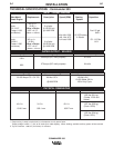
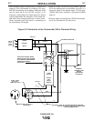
CONNECTION OF LN-15 TO THE COM-
MANDER 300
These connections instructions apply to both the LN-
15 Across-The-Arc and Control Cable models. The LN-
15 has an internal contactor and the electrode is not
energized until the gun trigger is closed. When the gun
trigger is closed the wire will begin to feed and the
welding process is started.
• Shut the welder off.
• For electrode Positive, connect the electrode cable
to the "+" terminal of the welder and work cable to
the "-" terminal of the welder. For electrode Negative,
connect the electrode cable "-" terminal of the welder
and work cable to the "+" terminal of the welder.
• Across-The-Arc Model:
Attach the single lead from the front of the LN-15
to work using the spring clip at the end of the lead.
This is a control lead to supply current to the wire
feeder motor; it does not carry welding current.
Control Cable Model:
Connect Control Cable between Engine Welder
and Feeder.
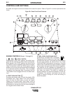
• Set the MODE switch to the "CV-WIRE " position.
• Across-The-Arc Model:
Set the "WELD TERMINALS" switch to "WELD
TERMINALS ON"
Control Cable Model:
Set the "WELD TERMINALS" switch to
"REMOTELY CONTROLLED"
• Set the "WIRE FEEDER VOLTMETER" switch to
either "+" or "-" as required by the electrode polarity
being used.
• Set the "ARC CONTROL" knob to "0" initially and
adjust to suit.
CONNECTION OF AN NA-3 AUTOMATIC
WELDING SYSTEM TO THE COMMANDER
300
For connection diagrams and instructions for connect-
ing an NA-3 Welding System to the Commander 300,
refer to the NA-3 Welding System instruction manual.
The connection diagram for the LN-8 can be used for
connecting the NA-3.
CONNECTION OF AN LN-742 TO THE
COMMANDER 300 (FOR CODES ABOVE
10500 ONLY)
(Requires optional K1597-1, 42 VAC
Transformer Kit).
• Shut the welder off.
• Connect the LN-742 per instructions on the appro-
priate connection diagram in the DIAGRAMS sec-
tion.
• Set the “WIRE FEEDER VOLTMETER” switch to
either “+” or “-” as required by the electrode being
used.
• Set the “SELECTOR” switch to the “CV-WIRE” posi-
tion.
• Adjust the “ARC CONTROL” knob to desired
Crispness. SOFT for MIG and CRISP for Innershield.
• Set the “WELDING TERMINALS” switch to the
“REMOTELY CONTROLLED” position.
• Set the “IDLE” switch to the “AUTO” position. When
not welding, the Commander 300 engine will be at
the low idle speed.