


A-5
A-5
INSTALLATION
SP-135 PLUS
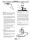
3. Attach the flow regulator to the cylinder valve and
tighten the union nut securely with a wrench. The
flow regulator for carbon dioxide must have a plas-
tic washer seated in the fitting that attaches to the
cylinder to prevent leakage. Refer to K1800-1 in
the accessories section.
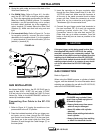
4. Refer to Figure A.6. Attach one end of inlet gas
hose to the outlet fitting of the flow regulator and
tighten the union nut securely with a wrench.
Connect the other end to the SP-135 PLUS Gas
Solenoid Inlet Fitting (5/8-18 female threads — for
CGA — 032 fitting). Make certain the gas hose is
not kinked or twisted.
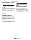
INPUT CONNECTIONS
Refer to Figure A.6.
The SP-135 PLUS has two input connections, the
power input cable, and the Gas Solenoid Inlet Fitting.
Both are located on the rear of the machine.
FIGURE A.6
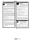
BUILDUP OF SHIELDING GAS may
harm health or kill.
• Shut off shielding gas supply
when not in use.
• SEE AMERICAN NATIONAL
STANDARD Z-49.1, “SAFETY IN
WELDING AND CUTTING” PUB-
LISHED BY THE AMERICAN
WELDING SOCIETY.
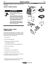
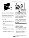
1. Chain the cylinder to a wall or other stationary sup-
port to prevent the cylinder from falling over.
Insulate the cylinder from the work circuit and earth
ground.
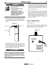
FIGURE A.5
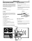
2. With the cylinder securely installed, remove the
cylinder cap. Stand to one side away from the out-
let and open the cylinder valve very slightly for an
instant. This blows away any dust or dirt which may
have accumulated in the valve outlet.
BE SURE TO KEEP YOUR FACE AWAY FROM THE
VALVE OUTLET WHEN “CRACKING” THE VALVE.
Never stand directly in front of or behind the flow
regulator when opening the cylinder valve. Always
stand to one side.
WARNING
WARNING
Cylinder Valve
Gas Hose
Flow Regulator
Gas Solenoid
Inlet Fitting
Power
Input
Cable