


SP-135 PLUS
B-5
B-5
OPERATION
Shielding Gas
When using the GMAW process, a cylinder of shield-
ing gas, must be obtained. Refer to the ACCES-
SORIES section for more information about selecting
gas cylinders for use with the SP-135 PLUS.
1. For CO
2
, open the cylinder very slowly. For argon-
mixed gas, open cylinder valve slowly a fraction of
a turn. When the cylinder pressure gauge pointer
stops moving, open the valve fully.
2. If using a regulator with an adjustable flow meter,
close the gun trigger and adjust the flow to give 15
– 20 cubic ft per hour (CFH) (7 – 10 I/min) [use 20
-– 25 CFH (10 – 12 I/min) when welding out of
position or in a drafty location for CO
2
]. For argon
mixed gas, trigger to release gas pressure, and
turn off the adjust the flow to give 25 – 30 CFH
(12 – 14 I/min).
3. Keep the cylinder valve closed, except when using
the SP-135 PLUS. When finished welding:
a) Close the cylinder valve to stop gas flow.
b) Depress the gun trigger briefly to release the
pressure in the gas hose.
c) Turn off the SP-135 PLUS.
Making A Weld
1. See Recommended Processes And Equipment
section for selection of welding wire and shielding
gas and for range of metal thicknesses that can be
welded.
2. See the Application Chart on the inside of wire
feed section door for information on setting the
SP-135 PLUS controls.
3. Set the Voltage (“V”) and Wire Speed (“olo’”) con-
trols to the settings suggested for the welding wire
and base metal thickness being used.
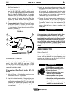
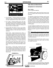
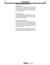
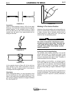
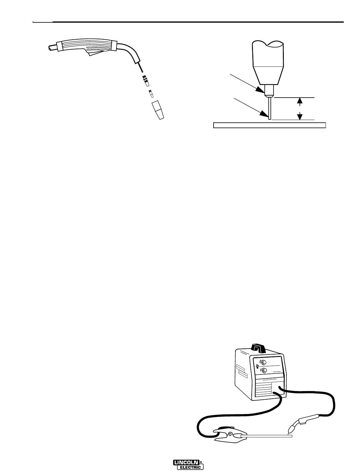
FIGURE B.6FIGURE B.5
Gun Handle
Gas Diffuser
Contact Tip
Gas Nozzle
4. Check that the polarity is correct for the welding
wire being used and that the gas supply, if
required, is turned on.
5. When using Innershield electrode, remove the gas
nozzle and install the gasless nozzle. This will
improve visibility of the arc and protect the gas dif-
fuser from weld spatter. Refer to the MAINTE-
NANCE section for details on nozzle replacement.
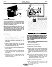
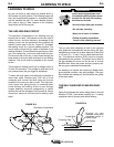
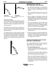
6. Refer to Figure B.7. Connect work clamp to metal
to be welded. Work clamp must make good elec-
trical contact to the workpiece. The workpiece
must also be grounded as stated in “Arc Welding
Safety Precautions” in the beginning of this manu-
al.
7. Position gun over joint. End of wire may be lightly
touching the work.
8. Lower welding helmet, close gun trigger, and
begin welding. Hold the gun so the contact tip to
work distance is about 3/8 inch (10 mm).
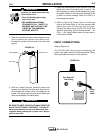
3/8" – 1/2" Electrical Stickout
Contact Tip
Wire Electrode
FIGURE B.7
WORKPIECE
GUN CABLE
ARC
WORK CLAMP