


A-4
INSTALLATION
RANGER 305D
A-4
SPARK ARRESTER
Some federal, state or local laws may require that
gasoline or diesel engines be equipped with exhaust
spark arresters when they are operated in certain
locations where unarrested sparks may present a fire
hazard. The standard muffler included with this welder
does not qualify as a spark arrester. When required by
local regulations, a suitable spark arrester, such as
the K1898-1 must be installed and properly main-
tained.
An incorrect spark arrestor may lead to damage to
the engine or adversely affect performance.
------------------------------------------------------------------------
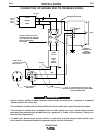
REMOTE CONTROL
The RANGER 305D is equipped with a 6-pin and a
14-pin connector. The 6-pin connector is for connect-
ing the K857 or K857-1 Remote Control or for TIG
welding, the K870 foot Amptrol or the K936-2 hand
Amptrol. When in the CC-STICK, DOWNHILL PIPE,
or CV-WIRE modes and when a remote control is
connected to the 6-pin Connector, the auto-sensing
circuit automatically switches the OUTPUT control
from control at the welder to remote control.
When in TOUCH START TIG mode and when a
Amptrol is connected to the 6-Pin Connector, the
OUTPUT dial is used to set the maximum current
range of the CURRENT CONTROL of the Amptrol.
The 14-pin connector is used to directly connect a
wire feeder control cable. In the CV-WIRE mode,
when the control cable is connected to the 14-pin con-
nector, the auto-sensing circuit automatically makes
the Output Control inactive and the wire feeder volt-
age control active
NOTE: When a wire feeder with a built in welding
voltage control is connected to the 14-pin connec-
tor, do not connect anything to the 6-pin connec-
tor.
------------------------------------------------------------------------
ELECTRICAL CONNECTIONS
MACHINE GROUNDING
Because this portable engine driven welder creates its
own power, it is not necessary to connect its frame to
an earth ground, unless the machine is connected to
premises wiring (home, shop, etc.)
To prevent dangerous electric shock, other equipment
to which this engine driven welder supplies power
must be grounded to the frame of the welder using a
grounded type plug or be double insulated.
When this welder is mounted on a truck or trailer, its
frame must be electrically bonded to the metal frame
of the vehicle. Use a #8 or larger copper wire connect-
ed between the machine grounding stud and the
frame of the vehicle. When this engine driven welder
is connected to premises wiring such as that in a
home or shop, its frame must be connected to the sys-
tem earth ground. See further connection instructions
in the section entitled "Standby Power Connections"
as well as the article on grounding in the latest
National Electrical Code and the local code.
In general, if the machine is to be grounded, it should
be connected with a #8 or larger copper wire to a solid
earth ground such as a metal water pipe going into the
ground for at least ten feet and having no insulated
joints, or to the metal framework of a building which
has been effectively grounded. Do not ground the
machine to a pipe that carries explosive or com-
bustible material.
The National Electrical Code lists a number of alter-
nate means of grounding electrical equipment. A
machine grounding stud marked with the symbol
is provided on the front of the welder.
WELDING TERMINALS
The RANGER 305D is equipped with a toggle switch
for selecting "hot" welding terminal when in the "WELD
TERMINALS ON" position or "cold" welding terminal
when in the "REMOTELY CONTROLLED" position.
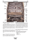
WELDING OUTPUT CABLES
With the engine off connect the electrode and work
cables to the output studs. The welding process dic-
tates the polarity of the electrode cable. These con-
nections should be checked periodically and tightened
with a 3/4" wrench.
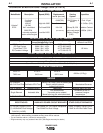
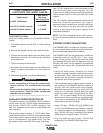
Table A.1 lists recommended cable sizes and lengths
for rated current and duty cycle. Length refers to the
distance from the welder to the work and back to the
welder. Cable diameters are increased for long cable
lengths to reduce voltage drops.
WARNING
CAUTION