


The 240 VAC output can be split to provide two sepa-
rate 120 VAC outputs with a max permissible current
of 44 Amps per output to two separate 120 VAC
branch circuits (these circuits cannot be paralleled).
Output voltage is within ± 10% at all loads up to rated
capacity.
The 120 V auxiliary power receptacles should only be
used with three wire grounded type plugs or
approved double insulated tools with two wire plugs.
The current rating of any plug used with the system
must be at least equal to the current capacity of the
associated receptacle.
NOTE: The 240 V receptacle has two 120 V circuits,
but are of opposite polarities and cannot be paral-
leled.
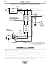
STANDBY POWER CONNECTIONS
The RANGER 305D is suitable for temporary, stand-
by or emergency power using the engine manufactur-
er’s recommended maintenance schedule.
The RANGER 305D can be permanently installed as
a standby power unit for 240 VAC, 3 wire, single
phase, 44 amp service. Connections must be made
by a licensed electrician who can determine how the
120/240 VAC power can be adapted to the particular
installation and comply with all applicable electrical
codes.
• Install the double-pole, double-throw switch
between the power company meter and the premis-
es disconnect. Switch rating must be the same or
greater than the customer’s premises disconnect
and service over current protection.
• Take necessary steps to assure load is limited to
the capacity of the RANGER 305D by installing a
50 amp, 240 VAC double pole circuit breaker.
Maximum rated load for each leg of the 240 VAC
auxiliary is 44 amperes. Loading above the rated
output will reduce output voltage below the allow-
able - 10% of rated voltage which may damage
appliances or other motor-driven equipment and
may result in overheating of the RANGER 305D
engine and/or alternator windings.
• Install a 50 amp, 120/240 VAC plug (NEMA Type
14-50) to the double-pole circuit breaker using No.
6, 4 conductor cable of the desired length. (The 50
amp, 120/240 VAC plug is available in the optional
K802R plug kit or as part number T12153-9.)
• Plug this cable into the 50 Amp, 120/240 Volt
receptacle on the RANGER 305D case front.
A-5
INSTALLATION
RANGER 305D
A-5
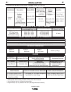
TABLE A-1
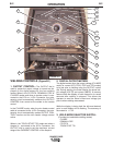
CABLE INSTALLATION
Install the welding cables to your RANGER 305D as
follows.
1. The diesel engine must be OFF to install welding
cables.
2. Remove the flanged nuts from the output terminals
.
3. Connect the electrode holder and work cables to the
weld output terminals. The terminals are identified
on the case front.
4. Tighten the flanged nuts securely.
5. Be certain that the metal piece you are welding (the
“work”) is properly connected to the work clamp and
cable.
6. Check and tighten the connections periodically.
• Loose connections will cause the output termi-
nals to overheat. The terminals may eventually
melt.
• Do not cross the welding cables at the output ter-
minal connection. Keep the cables isolated and
separate from one another.
------------------------------------------------------------------------
AUXILIARY POWER RECEPTACLES
The auxiliary power of the RANGER 305D consists of
two 20 Amp-120 VAC (5-20R) duplex receptacles and
one 50 Amp 120/240 VAC (14-50R) receptacle. The
240 VAC receptacle can be split for single phase 120
VAC operation.
The auxiliary power capacity is 10,500 watts Peak,
10000 Watts Continuous of 60 Hz, single phase power.
The auxiliary power capacity rating in watts is equiva-
lent to volt-amperes at unity power factor. The max
permissible current of the 240 VAC output is 44 amps.
TOTAL COMBINED LENGTH OF
ELECTRODE AND WORK CABLES
Cable Length
0-100Ft. (0-30meters)
100-150 Ft. (30-46m meters)
150-200 Ft. (46-61 meters)
Cable Size for
305 Amps
100% Duty Cycle
1 / 0 AWG
2 / 0 AWG
3 / 0 AWG
CAUTION