


B-2
OPERATION
B-2
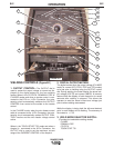
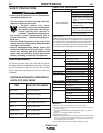
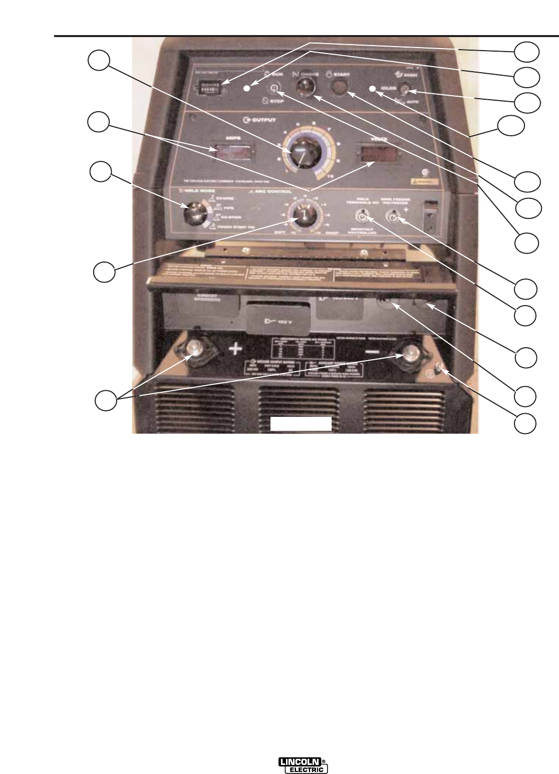
WELDING CONTROLS (Figure B.1)
1. OUTPUT CONTROL:
The OUTPUT dial is
used to preset the output voltage or current as dis-
played on the digital meters for the four welding
modes. When in the CC-STICK, DOWNHILL PIPE or
CV-WIRE modes and when a remote control is con-
nected to the 6-Pin or 14-Pin Connector, the auto-
sensing circuit automatically switches the OUTPUT
CONTROL from control at the welder to the remote
control.
In the CV-WIRE mode, when the wire feeder control
cable is connected to the 14-Pin Connector, the auto-
sensing circuit automatically makes OUTPUT CON-
TROL inactive and the wire feeder voltage control
active.
When in the TOUCH START TIG mode and when a
Amptrol is connected to the 6-Pin Connector, the
OUTPUT dial is used to set the maximum current
range of the CURRENT CONTROL of the Amptrol.
2. DIGITAL OUTPUT METERS
The digital meters allow the output voltage (CV-WIRE
mode) or current (CC-STICK, PIPE and TIG modes)
to be set prior to welding using the OUTPUT control
dial. During welding, the meter display the actual out-
put voltage (VOLTS) and current (AMPS). A memory
feature holds the display of both meters on for seven
seconds after welding is stopped. This allows the
operator to read the actual current and voltage just
prior to when welding was ceased.
While the display is being held the left-most decimal
point in each display will be flashing. The accuracy of
the meters is +/- 3%.
3. WELD MODE SELECTOR SWITCH:
(Provides four selectable welding modes)
CV-WIRE
DOWNHILL PIPE
CC-STICK
TOUCH START TIG
RANGER 305D
1
10
7
4
9
5
8
11
12
13
6
15
14
17
16
2
3
FIGURE B.1