


B-4
OPERATION
B-4
Operating the starter motor for more than 5 seconds
can damage the motor. If the engine fails to start,
release the switch and wait 10 seconds before opera-
tion the starter again. Do NOT push the START button
while the engine is running because this can damage
the ring gear and/or the starter motor.
-----------------------------------------------------------------------------
NOTE: When starting a Ranger® 250 for the first time, or
after an extended period of time of not operating, it will
take longer than normal because the fuel pump has to fill
the fuel line and carburetor.
FOR SUBARU ROBIN ENGINES
If engine is already warm starting should be done with
one half or no choke applied.
STOPPING THE ENGINE
Remove all welding and auxiliary power loads and allow
the engine to run at low idle speed for a few minutes to
cool the engine.
Stop the engine by placing the RUN-STOP in the STOP
position.
NOTE: A fuel shut off valve is not required on the
Ranger® 250 because the fuel tank is mounted below the
engine.
WELDER OPERATION
DUTY CYCLE is the percentage of time the load is
being applied in a 10 minute period. For example, a 60%
duty cycle represents 6 minutes of load and 4 minutes of
no load in a 10 minute period.
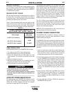
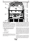
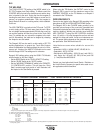
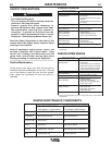
RANGER® 250
CAUTION
Kohler CH23S
23HP @ 3600 RPM
Gal./Hr (Liters/Hr)
Low Idle - No Load 0.6 (2.3)
2400 R.P.M.
High Idle - No Load 0.8 (3.0)
3700 R.P.M.
DC Weld Output 1.40 (5.3)
250 Amps @ 28 Volts
Auxiliary Power 1.64 (6.2)
9,500 Watts Continuous
Subaru Robin EH65
22HP @ 3600 RPM
Gal./Hr (Liters/Hr)
0.5 (1.9)
0.8 (3.0)
1.6 (5.9)
1.9 (7.2)
CH23/EH65 HOURS
Approx. Run Time for
12 Gallon Tank (Hours)
20 / 24
15 / 15
8.6 / 7.5
7.3 / 6.3
TYPICAL RANGER® 250 FUEL CONSUMPTION
DC STICK WELDING
The Ranger® 250 can be used with a broad range of DC
stick electrodes.
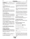
The MODE switch provides two stick welding settings as
follows:
CONSTANT CURRENT (CC-STICK) WELDING
The CC-STICK position of the MODE switch is designed for
flat, horizontal and vertical-up welding with all types of elec-
trodes, especially low hydrogen. The output CONTROL dial
adjusts the full output range for stick welding.
The ARC CONTROL dial sets the short circuit current (arc-
force) during stick welding to adjust for a soft or crisp arc.
Increasing the number from -10(soft) to +10(crisp) increases
the short circuit current and prevents sticking of the elec-
trode to the plate while welding. This can also increase spat-
ter. It is recommended that the ARC CONTROL be set to the
minimum number without electrode sticking. Start with the
dial set at 0.
DOWNHILL PIPE WELDING
This slope controlled setting is intended for "out-of-position"
and "down hill" pipe welding where the operator would like to
control the current level by changing the arc length. The out-
put CONTROL dial adjusts the full output range for pipe
welding. The ARC CONTROL dial sets the short circuit cur-
rent (arc-force) during stick welding to adjust for a soft or
more forceful digging arc (crisp). Increasing the number from
-10(soft) to +10(crisp) increases the short circuit current
which results in a more forceful digging arc. Typically a
forceful digging arc is preferred for root and hot passes. A
softer arc is preferred for fill and cap passes where weld
puddle control and deposition (“stacking” of iron) are key to
fast travel speeds. This can also increase spatter. It is rec-
ommended that the ARC CONTROL be set to the minimum
number without electrode sticking. Start with the dial set at 0.