


A-2
INSTALLATION
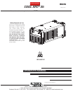
COOL ARC® 35
A-2
SAFETY PRECAUTIONS
Connecting the COOL ARC® 35 to a power
source:
1. Disconnect all power to the power source.
2. Turn the power source on its side revealing the Cooler
Access Panel on the bottom.
3. Loosen the fasteners and remove the Panel. Keep the fas-
teners to reattach the Panel.
4. Place the COOL ARC® 35 near the V310-T/V311-T and push
the lead harness from the cooler through the grommet in the
Access Panel that was just removed from the power source
(making sure that the direction of the leads going through the
panel is correct).
5. Attach the two plugs from the COOL ARC® 35 harness into
the mating receptacles inside the power source where the
Cooler Access Panel was removed (making sure that these
connectors “lock” into the mating receptacles).
6. Slide the Access Panel up the harness toward the power
source and reattach using the fasteners that were removed.
NOTE: Make sure that the grommet or the harness itself does
not put any stress on the connectors when closing up the Panel.
7. Place the power source on top of the cooler locating the feet
of the power source into the mating foot prints in the cooler
case front and back.
8. Secure the power source to the cooler with the four fasteners
that were included with the cooler.
9. Unscrew the coolant reservoir cap and remove the clear plug
(keep for transporting the cooler when filled with coolant).
The clear plug should never be installed when operating the
cooler - it will prevent proper venting. Fill the reservoir with
coolant per the Recommended Coolant section on the TECH-
NICAL SPECIFICATIONS page. The reservoir is full when
the coolant reaches a level just below the cap.
10. The system is now ready for water cooled torch
applications.
Connecting a water-cooled torch:
1. Disconnect all power to the power source.
2. Assemble the torch per the instructions included
with the torch and Twist-mate Adapter.
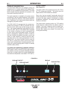
3. Connect the HOT water return hose (normally RED)
to the Coolant Inlet on the front of the cooler.
Depending on the type of hose connectors on the
torch, it may be necessary to use brass couplers
that are included with the cooler.
4. Connect the COLD water to the torch hose (normal-
ly BLUE) to the Coolant Outlet on the front of the
cooler.
5. Attach the twist-mate from the torch to the DC neg-
ative (-) Electrode/Gas output terminal on the power
source.
6. Turn the power ON to the power source.
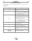
7. The cooler Display will illuminate and go through
initialization. The cooler will enter into standby
mode if a Stick welding mode is selected.
8. Press the push button on the cooler to begin the
priming procedure. The cooler display will show
dashed lines moving in a circular motion.
9. The torch is now ready for water-cooled welding
applications.
Note: If E43 alarm codes are encountered, the torch
has not been properly primed. Run the priming
procedure again by pressing the cooler push
button.
WARNING
ELECTRIC SHOCK can kill.
• Disconnect input power by remov-
ing plug from V310-T/V311-T before
working inside Cooler.
• Do not touch electrically “hot”
parts inside Cooler.
• Have qualified personnel do the installation,
maintenance and troubleshooting work.
----------------------------------------------------------------------