


!&+,$$,!'&
*847G;<F8AG<E8<AFG4??4G<BAF86G<BA589BE8LBH
FG4EG<AFG4??4G<BA
+,1(*-,!'&+
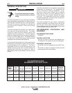
$,*!+ '#64A><??
Q BABGGBH6;8?86GE<64??L?<I8C4EGF
FH6;4FBHGCHGG8E@<A4?FBE<AG8E
A4?J<E<A:
Q !AFH?4G8LBHEF8?99EB@G;8JBE>4A7
:EBHA7
Q ?J4LFJ84E7EL<AFH?4G<A::?BI8F
------------------------------------------------------------------------
'&&,!'& ,' */!, *1
,'/$-&
BAA86G<A:4#BE#GB4$<A6B?A
8878ETBEF@4??8E7<4@8G8EJ<E8
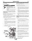
The #BE# will connect to any wire
feeder with a Lincoln style gun receiver bushing (i.e.
LN-8, LN-9, LN-25 or any feeder with a K1500-1
bushing installed). (See Figure A.1)
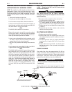
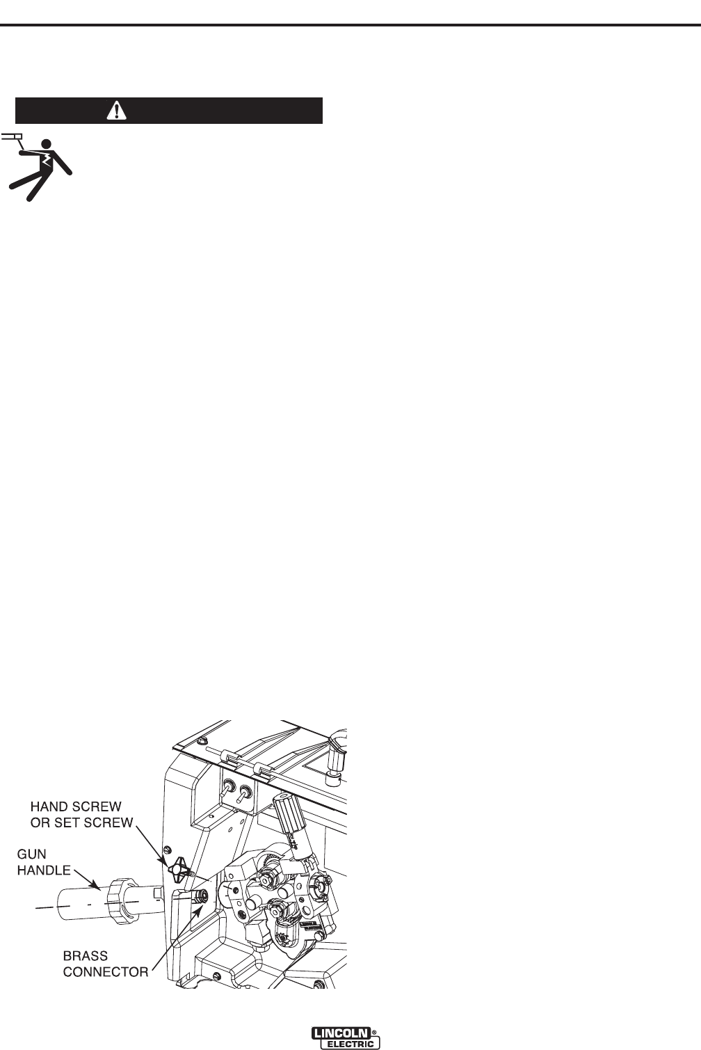
1. Check that the drive roll(s) and feeder guide
tubes are appropriate for the electrode size
being used.
2. Fully push the brass connector end of the gun
cable into the conductor block on the outgoing
side of the feeder wire drive. Secure the cable
using the hand screw or set screw in the con-
ductor block.
3. Insert the round connector of the control cable
into the mating connector on the front of the
wire feeder.
!-*
BAA86G<BAGB74CG878878EF$<A6B?A
$&+,,4A7(BJ8E887J<E898878EF
TBEF@4??8E7<4@8G8EJ<E8
The # gun and cable assembly will connect
easily to any properly adapted feeder.
1. Check that the adapter and feeder outgoing
guide, as well as the drive roll, are appropriate
for the electrode size being used. On Lincoln
feeders, check that the K1500-2 gun adapter is
in place.
2. Fully push the brass connector end of the gun
cable into the brass adapter on the outgoing side
of the feeder wire drive. Secure the cable using
the hand screw or set screw in the adapter.
3. Insert the round connector of the control cable
into the mating connector on the front of the wire
feeder.
'&.*+!'& '## '*
# ,'/$/!, ', * /!*
*+
Prepare gun and determine correct connector kit
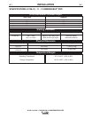
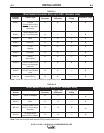
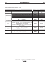
1. Determine which K466 or K613 kit is required for
your system using (Tables A.1 and A.2) in the
front part of the Installation Section.
2. Remove the insulator, tip holder and gun control
cable.
3. Lay gun and cable out straight on a flat surface.
4. Loosen set screw located in the brass cable con-
nector at the wire feeder end of the cable using
the 5/64 (2.0 mm) Allen wrench. Pull liner out of
cable.
5. Remove the brass cable connector from the
feeder end of the gun using the wrench provided.
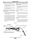
6. Install the new connector kit using the appropri-
ate procedure which follows.
##!AFG4??4G<BABE%<??8E98878EF
1. Remove brass cable connector (see Figure A.2)
from the kit and screw it on to the feeder end of
the gun cable. Tighten the connection with the
wrench provided.
2. Attach the round connector of the gun control
cable provided to the trigger connector on the
front of the Miller feeder.
##&#!&&*+ !$R(*'
/*&!&