


!&+,$$,!'&
##&#!&&*+ !$R(*'
2. Attach the round connector of the gun control
cable provided to the trigger connector on the
front of the Lincoln Feeder.
!AFG4??4A7,E<@G;845?8$<A8E
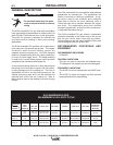
Installation of (KP44 and KP45 series liners)
1. Lay the gun and cable out straight on a flat sur-
face.
2. Make sure that the set screw in the connector
end is backed out so as not to damage liner or
liner bushing. Remove and save the tip holder,
contact tip and insulator from the end of the gun
tube assembly.
3. Insert a new untrimmed liner into the connector
end of the cable. Be sure the liner bushing is
stenciled appropriately for the wire size being
used.
4. Be sure to fully seat the liner bushing in the con-
nector and:
For all connector kits except K466-3, K466-4 and
K613-3, tighten the set screw in the cable connector.
'*
For K466-3, K466-4 and K613-3, screw in the con-
nector cap provided in the kit until it seats on the
face of the bushing. Then insert the appropriate
piece of liner material into the connector cap and
tighten the set screw. Three pieces of liner material
are included in these connector kits to help guide the
electrode through the connector cap. The piece with
the smallest inner diameter is designed for .045" (1.2
mm) maximum diameter electrode and the other lin-
ers fit the following wires (maximum size) in order of
increasing inside diameter: 1/16” (1.6 mm), 5/64”
(2.0 mm), 3/32” (2.4 mm) and 1/8” (3.2 mm).
&', ,;8@4K<@H@J<E8F<M89BE4#4A7
#<FT,;8E89BE8G;8T4A7
T?<A8EF4E8ABG<A6?H787J<G;G;8F8
><GF
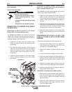
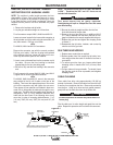
5. Be sure the cable is straight and then trim the
liner flush with the end of the gun tube.
6. Remove the gun tube and trim an additional
9/16” (12.7 mm) of material from the end of the
liner (a 9/16” gage is included on the wrench
supplied with the gun).
7. Replace the gun tube and tighten the clamping
screw to secure it.
8. Reassemble the tip holder, insulator, and con-
tact tip onto the end of the gun tube.
'&&,-&+,'/!**
BAA86G<BAGB%<??8E8878EF
Using the Gun and cable assemblies which were
assembled with a K466-3 or K613-3 connection kit in
the beginning of this Installation Section will connect
easily to a variety of popular Miller wire feeders.
1. Check that the gun liner, connector cap liner,
and drive rolls are appropriate for the electrode
size being used.
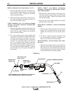
2. Fully push the brass connector end of the gun
and cable into the connector receptacle on the
outgoing side of the feeder wire drive. Tighten
the hand screw to clamp down on the connec-
tor.
3. Insert the control cable plug from the feeder trig-
ger circuit into the mating socket on the gun
cable feeder end handle.
BAA86G<BAGB B54EG8878EF
Using the Gun and cable assemblies which were
assembled with a K466-4 connection kit in the begin-
ning of this Installation Section will connect easily to a
variety of Hobart wire feeders.
1. Check that the gun liner, connector cap liner,
and drive rolls are appropriate for the electrode
size being used.
2. Fully push the brass connector end of the gun
and cable into the connector receptacle on the
outgoing side of the feeder wire drive. Tighten
the hand screw to clamp down on the connec-
tor.
3. Insert the control cable plug from the feeder trig-
ger circuit into the mating socket on the gun
cable feeder end handle.
BAA86G<BAGB$,8674CG878878EF
Using the Gun and cable assemblies which were
assembled with a K466-5 connection kit in the begin-
ning of this Installation Section will connect easily to
an L-Tec feeder equipped with an L-Tec feeder con-
nector assembly.
1. Check that the adapter and feeder outgoing
guide as well as the drive roll, are appropriate
for the electrode size being used.