


Py
thon-
P
lus
O
wner's Manual -
P
a
g
e
9
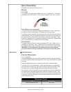
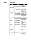
Troubleshootin
g
G
uid
e
R
e
g
ardless o
f
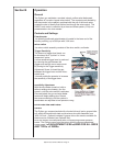
which torch or
f
eeder used, all MK Products’ push-pull
g
uns
op
erate on the same
p
rinci
p
le. The slave motor in the feeder runs at a fast,
constant speed, but has very low torque. It is always trying to
f
eed more wire
t
han the torch motor wants, and when the motor
g
ets all it wants, it slows the
slave motor, preventin
g
a bird’s nest. Because of the low torque produced b
y
th
e s
l
ave motor, a
b
ra
k
e system
i
s use
d
to prevent w
i
re overrun rat
h
er t
h
an
t
ension. The dra
g
ad
j
ustment in the
f
eeder is used simpl
y
to keep the wire
sli
g
htl
y
taut, so it will not pull off the spool while feedin
g
wire.
T
he high torque 24VD
C
torch motor is controlled by a solid state speed
control located in the feeder, and a
p
ot located in the torch. The torch motor,
p
otentiometer, and micro switch are connected to the cabinet/control box via
a control cable and Amphenol connector. I
f
this cable becomes dama
g
ed, a
variet
y
of s
y
mptoms can occur, dependin
g
on which wire
(
s
)
break. To test,
check each wire for continuity and shorts.
R
emember, the micro switch in the torch activates both the slave motor and
t
orch motor circuits in the cabinet. Therefore
,
if the slave motor and brake
solenoid operate, but the torch does not, look more toward the torch motor’s
24V circuits, speed control, control cable, or the torch motor. If nothin
g
op
erates, look more toward the slave motor
’
s in
p
ut, micro switch leads, or
micro switch.
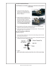
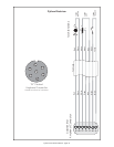
Testing The
G
u
n
R
e
f
erence the "W" clocked torch wiring diagram on
t
h
e
P
yt
h
on
®
Electrical Diagram for information
®
a
b
out p
i
n-outs an
d
l
ocat
i
ons.
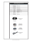
M
otor Chec
k
R
emove the torch connector
f
rom the cabinet.
U
sin
g
the torch Amphenol connector, check the resistance across pins
“
A”
an
d
“B
” (motor leads). The resistance across the motor should be between
5
-
10
o
hm
s
as the potentiometer is turned.
If an o
p
en circuit or short exist, check the motor leads and motor
i
n
d
epen
d
ent
l
y.
Testing the Potentiometer - “W”
C
locke
d
U
sin
g
the torch Amphenol connector, check the resistance across pin
“
D”
(
wiper) and pin “C
”
. The resistance should vary from
0
- 5K ohm
s
as t
h
e
potentiometer is turned.
C
heck the resistance across
p
in
“
D
”
(
wiper
)
and pin “
G”
. Th
e
r
es
i
s
t
a
n
ce
should vary from 5K - 0 ohms as t
h
e
p
otent
i
ometer
i
s turne
d
.
Testing the Micro
S
witc
h
U
sin
g
the torch Amphenol connector, check for continuit
y
across pins
“
E”
a
n
d
“
F
”
when the tri
gg
er is pressed.