


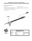
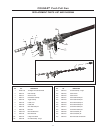
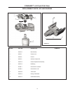

7
COUGAR™Push Pull Gun - OPERATING INSTRUCTIONS
Making A Weld
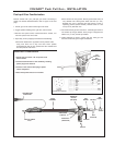
1 Check that the push-pull gun power, control, and gas connec-
tions are correct for the power source being used. Check that
the gas supply is turned on. Check wire push-pull for an ade-
quate supply of wire.
2. See "Procedure Settings", below for wire feed speed and
voltage settings. Set these controls depending on the weld-
ing wire and base metal thickness being used.
3. Connect work clamp to metal being welded. Work clamp must
make good electrical contact to the workpiece. The workpiece
must also be grounded as stated in "Arc Welding Safety
Precautions".
4. Connect power to welder and turn "ON".
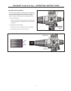
5. Prepare to purge gas line by first releasing wire drive. Push
wire drive release lever to the UP position, to avoid feeding
wire.
WARNING: Gun body and contact tip become
electrically energized when gun trigger is pressed
and remain so for several seconds
after trigger is released.
6. Press and hold gun trigger for about 5 seconds to purge gas
line. If adjustable regulator or metering valve is installed, adjust
gas flow per, "Setting Gas Flow Rate".
7. Re-engage wire drive by pushing release lever to down posi-
tion to feed wire.
8. Momentarily squeeze trigger and verify that wire feeds proper-
ly. Trim wire to approximately 1/4" (6 mm) from end of contact
tip.
WARNING: When using an open arc process, it is
necesary to use correct eye, ear, head,
and body protection.
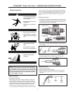
9. Position gun over joint at 10° pushing angle. End of wire may
be lightly touching the work.
10. Lower welding helmet, close gun trigger, and begin welding.
Hold the gun so that the contact tip to work distance is about
1/2 inch (13 mm).
11. To stop welding, release the gun trigger and then pull the gun
away from the work after the arc goes out.
12. When no more welding is to be done, close valve on gas cylin-
der, momentarily operate trigger to release gas pressure in line
and turn off power source.
13. Note that clogged tips can often be salvaged by peeling away
melted wire.
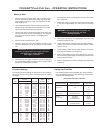
Procedure Settings
The following procedure settings for 4043 aluminum wire and argon
gas can be used as starting points for developing specific welding
procedures:
Wire Metal Wire Amps
Size Thickness Speed DC
in. (mm) ga. in. (mm) Arc Volts ipm (mpm) (+}
.030 (0.8) 22 .030 (0.8) 13-14
(1)
200 (5.1) 40
20 .036 (1.0) 13-14
(1)
240 (6.1) 40
18 .048 (1.2) 14-15
(1)
290 (7.4) 50
16 .060 (1.6) 15-16
(1)
340 (8.6) 60
14 .075 (2.0) 16-17
(1)
370 (9.4) 70
12 .105 (2.5) 16-18
(1)
430 (10.9) 90
10 .135 (3.5) 24-26 460 (11.7) 110
3/16 (5.0) 24-26 500 (12.7) 150
1/4 (6.0) 28-29 560 (14.2) 180
3/8 (10.0) 28-30 600 (15.2) 200
.035 (0.9) 22 .030 (0.8) 13-14
(1)
150 (3.8) 40
20 .036 (1.0) 13-14
(1)
175 (4.4) 40
18 .048 (1.2) 13-14
(1)
215 (5.5) 50
16 .060 (1.6) 14-16
(1)
250 (6.4) 60
14 .075 (2.0) 14-16
(1)
270 (6.9) 70
12 .105 (2.5) 16-18
(1)
320 (8.1) 90
10 .135 (3.5) 24-26 410 (10.4) 110
3/16 (5.0) 24-26 450 (11.4) 150
1/4 (6.0) 26-28 530 (13.5) 180
3/8 (10.0) 26-29 560 (14.2) 200
1/2 (12.0) 26-30 600 (15.2) 220
3/64(1.2) 10 .135 (3.5) 20-21
(1)
180 (4.6) 110
3/16 (5.0) 20-21
(1)
220 (5.6) 150
1/4 (6.0) 27-28 250 (6.4) 180
3/8 (10.0) 25-30 260 (6.6) 200
1/2 (12.0) 25-31 270 (6.9) 220
3/4 (20.0) 25-31 290 (7.4) 250
(1)
Short arc transfer.
Setting Gas Flow Rate
Gas handling systems having adjustable flow valves should be
set for the following argon flow rates, depending on base metal
thickness and welding position.
ARGON SHIELDING GAS FLOW RATES
Material Thickness Flow Rates
In Inches and (mm) Welding Position In cf/hr (l/mln)
1/16 (1.6 mm) Flat 30
(11.8)
3/32 to 3/16 Flat, Vertical, 35
(2.4 to 4.8 mm) Horizontal, Overhead (14)
1/4 to 3/8 Flat, Vertical, 35 (14)
(6.3 to 9.5 mm) Flat Vertical, 35 (16.5)
Horizontal, Overhead 40 (18.9)
3/4 (19 mm) Flat, Vertical 35 (16.5)
Horizontal, Overhead 40 (18.9)