


%&&!
'N 'N"$!'$(' %
! &&&" % !,, %&
&!
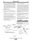
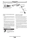
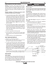
a. Choose the correct size contact tip for the elec-
trode being used (wire size is stenciled on the
side of the contact tip) and screw it snugly into the
gas diffuser.
b. Be
sure the nozzle insulator is fully screwed
onto the
gas diffuser
and does not block the gas
holes in the
diffuser.
c. Slip the appropriate gas nozzle onto the nozzle
insulator. Either a .62 inch (15.9 mm) or .50” (12.7
mm
I.D. slip-on gas nozzle may be used and should
be selected based on the welding application.
Choose the gas nozzle as appropriate for the
GMAW process to be used. Typically, the contact
tip end should be flush to .12 inch (3.1 mm)
extended for the short-circuiting transfer process
and .12 inch (3.1 mm) recessed for spray transfer.
For the Outershield (FCAW) process, 1/4 inch (6.3
mm) recess is recommended.
%&+"$'&! %
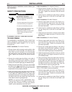
ELECTRIC SHOCK CAN KILL.
M<;<AA<B052920A?60.99F96C2=.?A@
@B05.@<BA=BAA2?:6;.9@<?6;A2?
;.9D6?6;4
---------------------------------------------------------------------
)$
! &! &!$
Connection to Lincoln Feeders
Gun cable assemblies which were assembled with a
K466-1 Connector Kit will connect easily to any
Lincoln LN-7, LN-8, LN-9, SP200 or LN-25 feeder.
a. Check that the drive roll(s) and feeder guide tubes
are appropriate for the electrode size being used.
b. Fully push the brass connector end of the gun
cable into the conductor block on the outgoing side
of the feeder wire drive. Secure the cable using the
hand screw or set screw in the conductor block.
c. Insert the control cable plug from the feeder trigger
circuit into the mating socket on the feeder end
cable handle (See K466-1
connector kit installation
to gun cable in this section
).
d. Slide the free end of the flexible hose onto the
barbed gas fitting on the front of the Lincoln feeder
(See K466-1 connector kit installation to gun cable in
this section) Move the
corresponding tubing clamp
down near the end of the tube to assure a good
gas seal
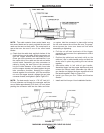
9 / 16” (14.3mm)
LINER TRIM
LENGTH
GUN TUBE ASSEMBLY
G
UN HANDLE
COLLAR ASSEMBLY
FEEDER END CABLE HANDLE
SET SCREW
GAS VENTED HOLE
NOZZLE ASSEMBLY
CONTACT TIP
DIFFUSER
LINER ASSEMBLY (LINER BUSHING TO BE SEATED
TIGHT AGAINST BRASS CABLE CONNECTOR)
INSULATOR
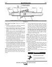
9 / 16” (14.3mm)
LINER TRIM
LENGTH
GUN TUBE ASSEMBLY
G
UN HANDLE
COLLAR ASSEMBLY
FEEDER END CABLE HANDLE
SET SCREW
GAS VENTED HOLE
NOZZLE ASSEMBLY
CONTACT TIP
DIFFUSER
LINER ASSEMBLY (LINER BUSHING TO BE SEATED
TIGHT AGAINST BRASS CABLE CONNECTOR)
INSULATOR
'$