


%&&!
'N 'N"$!'$(' %
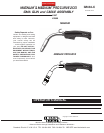
c. For L-Tec machines that require lead connections
to made at a terminal strip located within the
machine (L-Tec 225), a gun control cable with
forked
terminals is provided
. Connect the terminated
leads to the terminal strip. For a machine that
requires a twist-lock gun control cable connections,
continue
to use the L-Tec gun
control cable provided
with the L-Tec wire feeder connector assembly.
Connect the
twist-lock plug to the proper
receptacle
on the machine.
$ %&&!
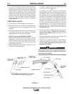
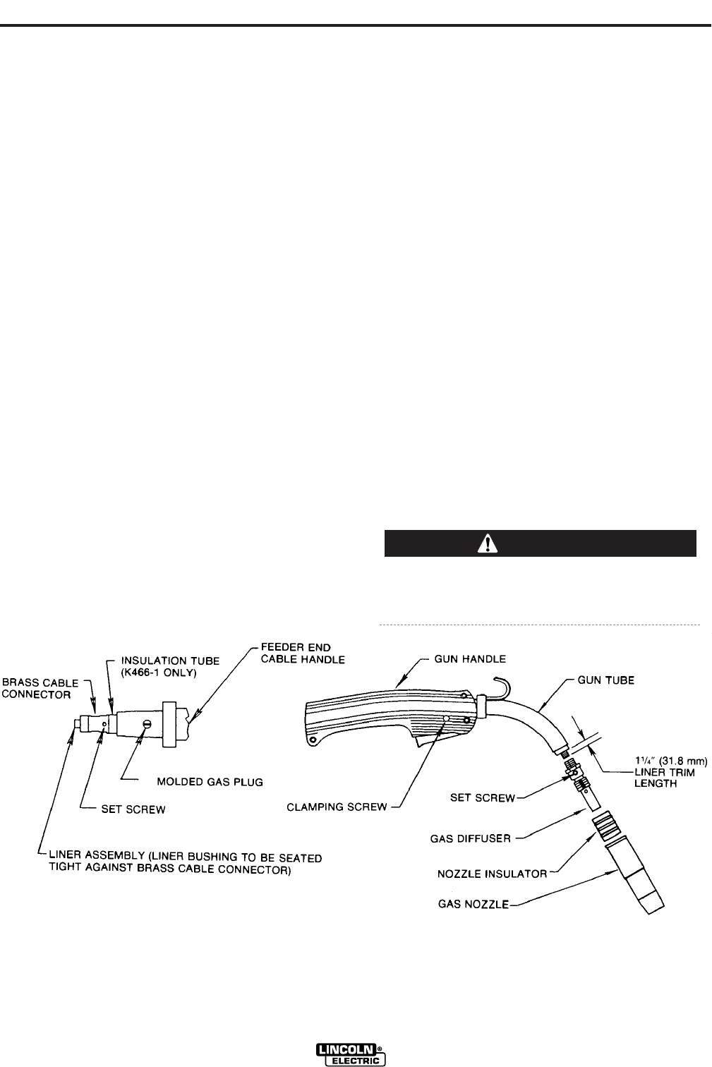
a. Lay the gun and cable straight on a flat surface.
b. Make sure that the set screw in the connector end
is backed out so as not to damage liner or liner
bushing.
c. Insert a new untrimmed liner into the connector
end
of the cable. Be sure the liner bushing
is stencilled
appropriately for the wire size being used.
NOTE: For liners series KP44N and KP45N
B
efore fully seating the liner bushing,
it will be
necessary to trim the liner’s inner tube flush with
the liner
bushing using a sharp blade
. After triming,
remove any burrs from inner tube and insure that
the opening is fully open.
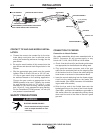
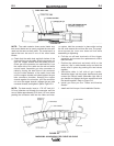
d. Before installing the gas diffuser, fully seat the liner
bushing in the connector and:
For K466-1, K466-2, K466-5 and K2950 tighten the
set screw in the cable connector.
OR
For K466-3 and K466-4, screw in the connector
cap provided in the kit until it seats on the face of
the bushing. Then insert the appropriate piece of
liner material into the connector cap and tighten the
set screw. Three pieces of liner material are includ-
ed i
n these connector kits to help guide the
electrode
through the connector cap. The piece with the
smallest inner diameter is designed for .045 inch,
(1.2 mm)
maximum diameter electrode. The
next
largest diameter is for 1/16 inch (1.6 mm maximum
diameter electrode. The
largest diameter piece of
liner
material is for 5/64 inch (2.0 mm) maximum
diameter electrode.
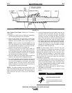
e. Be sure the cable is straight and then trim the liner
to the length shown in 64B?23<? or
64B?23<?. Remove any burrs from the
end of the liner.
f. Screw the gas diffuser onto the end of the gun tube
and tighten with the wrench provided.
g. Tighten the set screw in the side of the gas diffuser
against the cable liner using the Allen wren
ch
provided. <A2%2A@0?2D6@;<A3<B;1<;B;
.;1922;1<3
The screw should only be gently tightened.
Overtightening will split or collapse the liner and
cause poor wire feeding.
'$
'&!