


%&&!
'N 'N"$!'$(' %
! &!$& %&&!
&!'
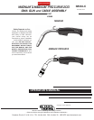
The MAGNUM® & MAGNUM® PRO CURVE 200
cable is shipped as a generic assembly and must be
assembled with either a K466-1, -2, -3, -4 or -5
Connector Kit.
;@A.99.A6<; (For Lincoln Feeders)
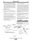
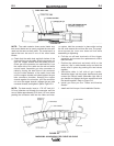
a. Remove brass cable connector and insulation tube
(see Figure A.1) from the K466-1 kit. Slide the insu-
lation tube onto the connector from the threaded
end and screw it onto the feeder end of the gun
cable. Tighten the connection with wrench provid-
ed.
b. Remove the molded gas plug fitting on the side of
the feeder end handle and replace it with the
barbed brass fitting provided in the kit. The included
wrench will fit both the gas plug and barbed fitting.
c. Attach the round connector of the gun control cable
provided to the trigger connector on the front of the
Lincoln feeder. !& Both the plug and socket are
keyed and must be properly oriented.
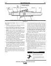
d. Place one tubing clamp onto each end of the flexi-
ble tubing provided, approximately 2 inch. (51 mm)
in from each end. Slide one end of the tubing onto
the barbed connector on the feeder end cable han-
dle (step b) and move the clamp down near the end
of the tube to assure a good gas seal.
!& An optional K481 MAGNUM® Fast-
Connect Gas Tube Kit is available to provide tool-
less gas tube connection to Lincoln wire feeders.
Install per the instructions sent with the kit.
$2.1A56@2;A6?26;@A.99.A6<;@20A6<;/23<?2F<B
@A.?A6;@A.99.A6<;
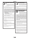
%&+"$'&! %
&$R%! can kill.
• Have an electrician install and ser-
vice this equipment.
• Turn the input power off at the fuse
box before working on equipment.
• Do not touch electrically hot parts.
• Be sure to discharge capacitors with
the procedure outlined in the
Maintenance Section of this manual
before working in that area of the
equipment.
---------------------------------------------------------------------
;@A.99.A6<; (For Adapted Feeders)
a. Remove brass connector (see Figure A-1) from the
K466-2 kit and screw it onto the feeder end of the
gun cable. Tighten the connection with the wrench
provided.
b. Check that the molded gas plug fitting is sealing
the gas fitting hole in the side of the feeder end
handle.
;@A.99.A6<; (For Miller Feeders)
a. Remove brass cable connector (see Figure A.1)
from the K466-3 kit and screw it onto the feeder
end of the gun cable. Tighten the connection with
the wrench provided.
b. Check that the molded gas plug fitting is sealing
the gas fitting hole in the side of the feeder end
handle.
c. Attach the round connector or the gun control cable
provided to the trigger connector on the front of the
Miller feeder.
;@A.99.A6<; (For Hobart Feeders)
a. Remove brass cable connector (see Figure A.1)
from the K466-4 kit and screw it onto the feeder
end of the gun cable. Tighten the connection with
the wrench provided.
b. Remove the molded gas plug fitting on the side of
the feeder end handle and replace it with the
barbed brass fitting provided in the kit.
The included
wrench will fit both the gas plug
and barbed fitting.
c. Attach the phone plug connector of the gun control
cable provided to the trigger connector on the front
of the Hobart feeder.
d. Place one tubing clamp onto each end of the flexi-
ble tubing provided, approximately 2 inch. (51 mm)
in from each end. Slide one end of the tubing onto
the barbed connector on the feeder end cable han-
dle (Step b) and move the clamp down near the
end of the tube to assure a good gas seal.
;@A.99.A6<; (For L-Tec Feeders equipped
with an L-Tec feeder connector assembly)
a. Remove brass cable connector (see Figure A.1)
from the K466-5 kit and screw it onto the feeder
end of the gun cable. Tighten the connection with
the wrench provided.
b. Check that the molded gas plug fitting is sealing
the gas fitting hole in the side of the feeder end
handle.
)$