


B-2 B-2
OPERATION
PRODUCT DESCRIPTION
The POWER MIG™ 215 is a complete semiautomatic
DC voltage arc welding machine built to meet NEMA
specifications. It combines a tapped transformer volt-
age power source with a constant speed wire feeder
to form a reliable robust performance welding system.
A simple control scheme, consisting of continuous full
range wire feed speed control, and 7 output voltage
tap selections provides versatility with ease of use and
accuracy.
Other features include a 2" (51 mm) O.D. wire reel
spindle with adjustable brake, an integral gas cylinder
mounting undercarriage, an adjustable Argon blend
flow regulator with cylinder pressure gauge and inlet
hose, a 15 ft. (3.6 m) Magnum 250L GMAW gun and
cable with fixed (flush) nozzle, a 7 ft. (2.1 m) power
cable with plug, and a 10 ft. (3.0 m) work cable with
clamp.
Optional Spool Gun and Adapter kit, Dual Cylinder
Mounting kit and Aluminum Feeding Kit for push feed-
ing with standard built in feeder are also available.
RECOMMENDED PROCESSES AND
EQUIPMENT
The POWER MIG 215 is recommended for GMA
welding processes using 10 to 44 lb (4.5 to 20 kg) 2"
(51 mm) I.D. spools or Readi-Reel
®
coils (with option-
al adapter) of .025" through .045" (0.6 – 1.2 mm) solid
steel, .035" (0.9 mm) stainless, 3/64" (1.2 mm) alu-
minum and .035 (0.9 mm), .045" (1.2 mm)
Outershield
®
; as well as .035" (0.9 mm) and .045" (1.2
mm) Innershield
®
self-shielding electrodes.
The POWER MIG is factory equipped to feed .035"
(0.9 mm) electrodes. It also includes a 200A, 60%
duty cycle (or 250A, 40% duty cycle) rated, 15 ft. (3.6
m) GMAW gun and cable assembly equipped for
these wire sizes. Use of GMAW processes requires a
supply of shielding gas.
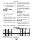
WELDING CAPABILITY
The POWER MIG 215 is rated at 215 amps @ 22
volts, at a 30% duty cycle based on a ten minute cycle
time. It is capable of higher duty cycles at lower output
currents. The tapped transformer design makes it
well suited for use with most portable or in-plant gen-
erating systems.
LIMITATIONS
The output voltage/current of the POWER MIG 215 is
subject to vary if the input power to the machine
varies, due to its tapped transformer power topology.
In some cases an adjustment of WFS preset and/or
voltage tap selection may be required to accommo-
date a significant drift in input power.
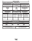
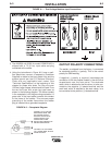
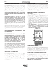
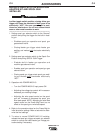
DESCRIPTION OF CONTROLS
See Figure B.1
1. Power ON/OFF Switch — Place the lever in the
"ON" position to energize the POWER MIG 215.
2. Voltage Control — Seven voltage tap selections
are provided Labeled "A" (minimum voltage)
through "G" (maximum voltage). It should only be
adjusted when not welding. The control selection
can be preset to the setting specified on the
Procedure Decal on the inside of the wire compart-
ment door.
3. Wire Speed Control — This controls the wire feed
speed from 50 – 700 inches per minute (1.2 – 17.8
m/min). Wire speed is not affected when changes
are made in the voltage control.
FIGURE B.1
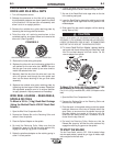
WIRE DRIVE ROLL
The drive rolls installed with the POWER MIG have
two grooves one for .035(0.9mm) wire and the other
for .045(1.2mm) wire. Drive roll size is indicated by the
stenciling on the exposed side of the drive roll.
WIRE SIZE CONVERSION PARTS
The POWER MIG 215 is rated to feed .025 through
.045" (0.6-1.2 mm) solid or cored electrode sizes.
The drive roll kits and Magnum 250L gun and cable
parts are available to feed different sizes and types of
electrodes. See Accessories section.
POWER MIG 215
33
22
11