


B-4 B-4
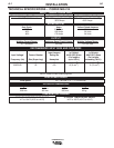
OPERATION
FEEDING WIRE ELECTRODE
When triggering, the electrode and
drive mechanism are electrically “hot”
relative to work and ground and
remain “hot” several seconds after
the gun trigger is released.
------------------------------------------------------------------------
NOTE: Check that drive rolls, guide plates and gun
parts are proper for the wire size and type being used.
Refer to Table C.1 in Accessories section.
1. Turn the Readi-Reel or spool until the free end of
the electrode is accessible.
2. While securely holding the electrode, cut off the
bent end and straighten the first six inches. (If the
electrode is not properly straightened, it may not
feed properly through the wire drive system).
3. Release the pressure on the idle roll by swinging
the adjustable pressure arm down toward the back
of the machine. Lift the cast idle roll assembly and
allow it to sit in an upright position. Leave the outer
wire guide plate installed. Manually feed the wire
through the incoming guide bushing and through
the guide plates (over the drive roll groove). Push a
sufficient wire length to assure that the wire has fed
into the gun and cable assembly without restriction.
Reposition the adjustable pressure arm to its origi-
nal position to apply pressure to the wire.
4. Press gun trigger to feed the electrode wire through
the gun.
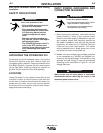
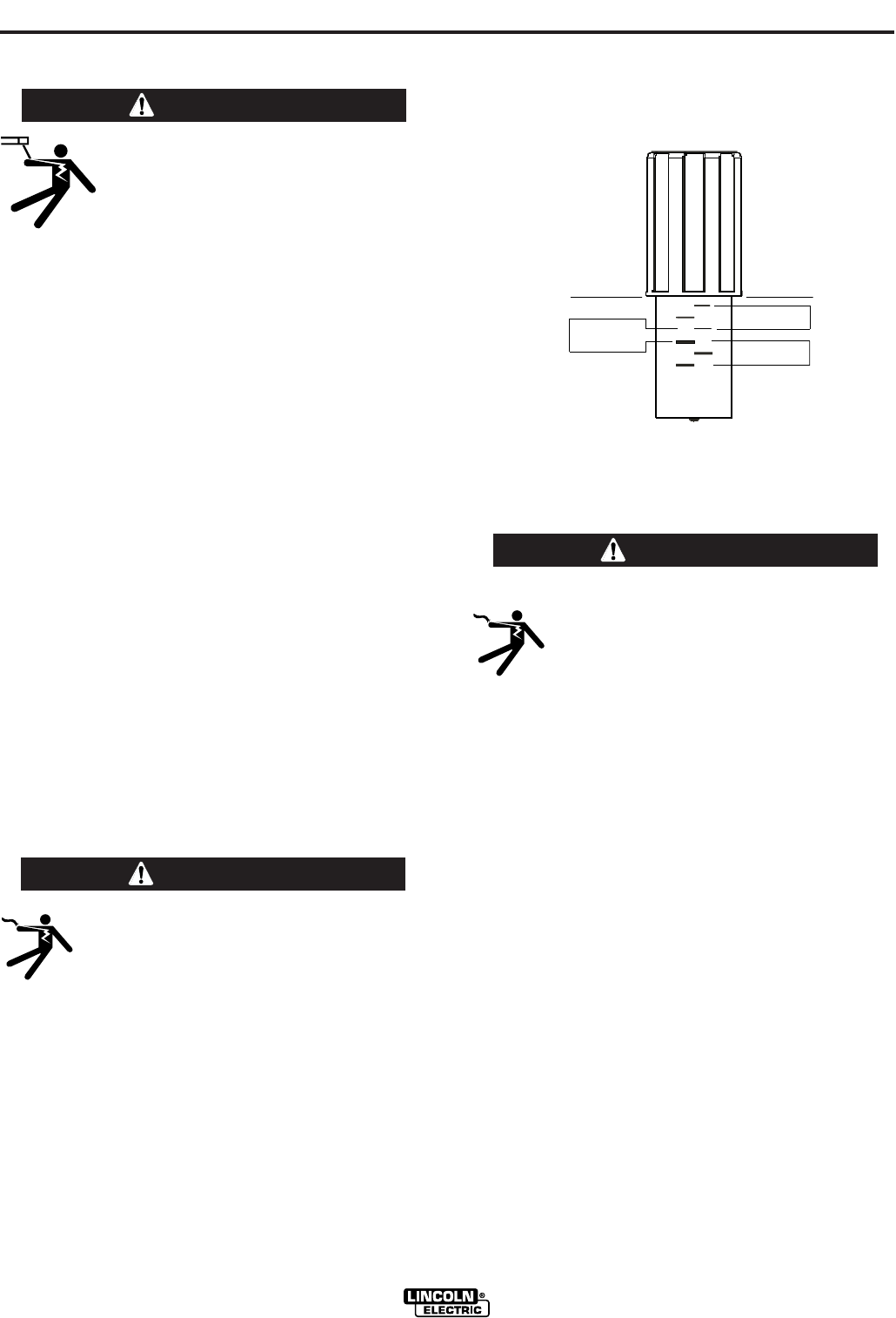
IDLE ROLL PRESSURE SETTING
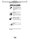
ELECTRIC SHOCK can kill.
• Turn the input power OFF at the weld-
ing power source before installation or
changing drive rolls and/or guides.
• Do not touch electrically live parts.
• When inching with the gun trigger, electrode
and drive mechanism are "hot" to work and
ground and could remain energized several sec-
onds after the gun trigger is released.
• Only qualified personnel should perform mainte-
nance work.
------------------------------------------------------------------------
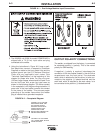
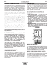
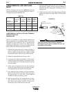
The pressure arm controls the amount of force the drive
rolls exert on the wire. Proper adjustment of both pres-
sure arm gives the best welding performance. For best
results, set both pressure arms to the same value.
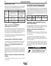
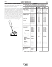
Set the pressure arm as follows (See Figure B.2a):
Aluminum wires between 1 and 3
Cored wires between 3 and 4
Steel, Stainless wires between 4 and 6
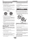
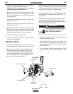
WIRE DRIVE CONFIGURATION
(See Figure B.2b)
Changing the Gun Receiver Bushing
ELECTRIC SHOCK can kill.
• Turn the input power OFF at the weld-
ing power source before installation or
changing drive rolls and/or guides.
• Do not touch electrically live parts.
• When inching with the gun trigger, electrode
and drive mechanism are "hot" to work and
ground and could remain energized several sec-
onds after the gun trigger is released.
• Only qualified personnel should perform mainte-
nance work.
-----------------------------------------------------------------------
Tools required:
• 1/4" hex key wrench.
Note: Some gun bushings do not require the use of
the thumb screw.
1. Turn power off at the welding power source.
2. Remove the welding wire from the wire drive.
3. Remove the thumb screw from the wire drive.
4. Remove the welding gun from the wire drive.
WARNING
WARNING
WARNING
POWER MIG 215
ALU MINU M
OUTERSHIELD
METALSHIELD
INN ERSHIELD
STEEL
S
TAINLESS
CORED WIRES
SOLID WIRES
6
1
3
2
5
4