


%*+##+ &%
*R
%)#*) '+ &%
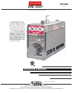
The SAE-300® is a heavy duty, engine driven, DC arc weld-
ing power source, capable of providing constant current out-
put for stick welding or DC TIG welding. This welder is
wound with all copper coils, rated at 300 amps/32 Volts, and
provides other Classic® features such as improved door
latches and stainless hinges. With the addition of the option-
al K623-1 Wire Feed Module
™
, the SAE-300® will provide
constant voltage output for running the LN-7, LN-23P, or
LN-25 wire feeders. (The Wire Feed Module is factory
installed on the K1643-8). The optional K924-5 Remote
Control Kit, provides a remote control rheostat for remote
fine current and open circuit voltage adjustment. See
Section C for description.
The SAE-300® has an Electronic Engine Protection System.
In the event of sudden low oil pressure or high coolant tem-
perature, the engine immediately shuts down. The SAE-
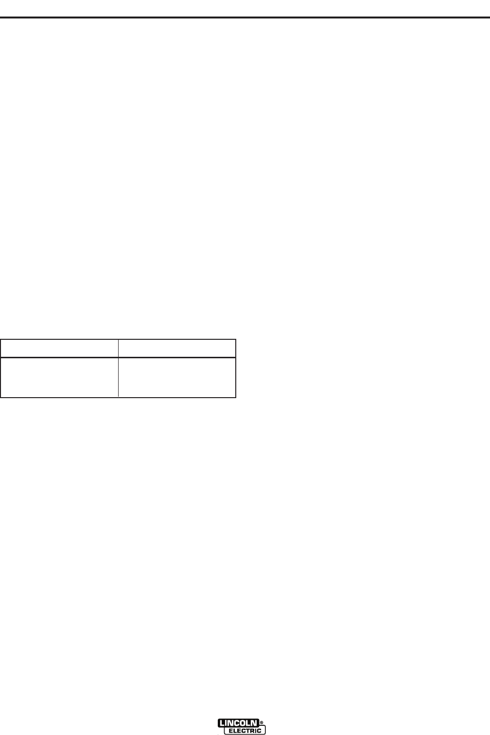
300® has a current range of 40-350 DC amps with output
ratings as follows:
These units are also capable of providing 3 KVA of 115/230
volts of 60 cycle AC auxiliary power.
The SAE-300® uses the Perkins 404D-22 industrial water-
cooled diesel engine.
* %+,)*
@?EC@='2?6=
The welder controls consist of a Reactor and a “Fine
Current Adjustment” rheostat located on the upper control
panel at the exciter end of the machine. The lower control
panel welder is equipped with a “Start” button, an “Ignition”
switch, an “Idler” control switch, and a “Glow Plug” button for
easier cold weather starting.
The lower control panel also contains an engine tempera-
ture gauge, a battery charging ammeter, an oil pressure
gauge, for auxiliary power consists of one 20 amp, 120VAC
(5-20R) duplex receptacle with GFCI protection and one 15
amp, 250VAC (6-15R) receptacle, protected by 2 pole, 15
Amp breaker.
==@AA6C.:?5:?8D - For long life and dependable
operation.
?8:?6 5=6C - The SAE-300® is equipped with an electron-
ic automatic engine idler. It automatically increases and
decreases engine speed H96?DE2CE:?82?5DE@AA:?8
H6=5:?8@CFD:?82FI:=:2CJA@H6C.
A built-in time delay permits changing electrodes before the
engine slows to its low idle speed.
The “Idler” control switch on the panel locks the idler in high
idle position when desired.
FI:=:2CJ'@H6C - 3.0 KVA of nominal 115/230V, 60Hz, AC.
Output voltage is maintained within ± 10% at all loads up to
rated capacity. (See Optional Features Section C for Power
Plug Kit.)
=2?<246)646AE24=6Protects the 20 amp, 120V
duplex receptacle. See the $2:?E6?2?46*64E:@? for
detailed information on testing and resetting of the GFCI.
-,'#/)'+#% #%"
)'+#
A GFCI protects the 120V auxiliary power
receptacle.
A GFCI (Ground Fault Circuit Interrupter) is a device to protect
against electric shock should a piece of defective equipment
connected to it develop a ground fault. If this situation should
occur, the GFCI will trip, removing voltage from the output of
the receptacle. If a GFCI is tripped see the MAINTENANCE
section for detailed information on testing and resetting it. A
GFCI should be properly tested at least once every month.
The 120 V auxiliary power receptacle should only be used with
three wire grounded type plugs or approved double insulated
tools with two wire plugs. The current rating of any plug used
with the system must be at least equal to the current capacity of
the associated receptacle.
.6=56C?4=@DFC6 - The complete welder is rubber mount-
ed on a rugged steel “C” channel base.
The output terminals are placed at the side of the machines
so that they are protected by the door. The output terminals
are labeled (+) and (-).
C2?<:?8*JDE6> - A 12 volt electric starter is standard.
:C=62?6C - Heavy duty two stage dry type.
$F77=6C - A muffler and stainless steel exhaust outlet elbow
are standard.
?8:?6@FC$6E6C - A meter to record hours of operation.
?8:?6'C@E64E:@?The system shuts the engine down in
the event of sudden low oil pressure or high coolant temper-
ature. A warning light on the control panel will indicate such
a fault. To reset the engine for restarting, turn the ignition
switch off then on.
&:=C2:?-2=G6A ball valve, hose and clamp are stan-
dard.
)6>@E6 @?EC@=- The Remote / Local Switch and
Receptacle are standard.
250A @ 30V
300A @ 32V
100%
60%
)+&,+',+ ,+00#