


B-10
OPERATION
IDEALARC SP-255
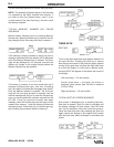
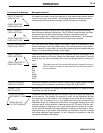
GUN SWITCHES
Gun Trigger Switch — Turns on arc voltage, wire
feeder, and gas solenoid (except with Innershield)
when closed. Also causes the screen to display the
Auto or Manual screens (depending on which mode it
is in), when the trigger is pulled. Turns off arc voltage,
wire feeder, and gas solenoid when opened.
NOTE: If using Slow Run-In, when the trigger is
pulled, the wire feeder feeds wire a low speed regard-
less of the set wire feed speed until the welding arc
starts or 2 seconds has elapsed. This feature
enhances starting and makes it easier to set the stick-
out. The 2 second limit permits high speed loading of
the gun and cable. To change Run-In mode, see
“Start Mode Selections” in this section.
Gun Thumbswitch (Magnum™ 250SP Only) —
Used to control wire feed speed, arc voltage, or selec-
tion of toggle memories 4 and 5. See IPM VOLTS key
and Toggle key for control details. The increase or
decrease function of the thumbswitch is the same as
the center and right arrow key pairs for IPM or VOLTS
setting. (See Arrow keys in “Setup Keys” section
for details.)
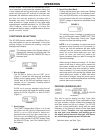
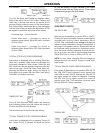
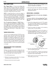
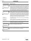
WIRE DRIVE ROLL
The drive roll provided with the SP-255 has two
grooves, one for .030-.035" (0.8-0.9 mm) solid steel
electrode, and the other for .045" (1.2 mm) solid steel
electrode. The welder is shipped with the drive roll
installed in the .030-.035" (0.8-0.9 mm) position as
indicated by the stencilling on the exposed side of the
drive roll. If .045" (1.2 mm) electrode is to be used or
one of the optional drive rolls is required (see
Accessories section). The drive roll must be reversed
or changed.
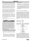
PROCEDURE FOR CHANGING
DRIVE ROLL
Different wire sizes may require changing the drive
roll. The applicable wire sizes are stamped on the
drive roll. Dual groove rolls must be installed so the
side with the proper wire size stamp faces out.
1 Turn off the power source.
2. Release the pressure on the idle roll by swinging
the pressure arm off the idle roll arm.
3. Remove the wire from the drive system.
4. Remove the thumbscrew from the drive roll. Turn
the drive roll over or change to another roll as
required. Reinstall the thumbscrew.
5. Be sure the gun liner and contact tip are properly
sized for wire being used. (See Gun and Cable
Maintenance section.)
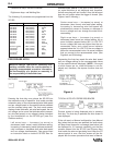
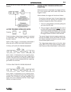
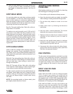
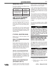
WIRE REEL LOADING
MOUNTING OF 22 TO 30 LB. READI-
REELS
To mount a 22-30 Ib. (10-14 kg) Readi-Reel
®
pack-
age using the optional Readi-Reel Adapter
(K363P).
1. Remove the locking collar from the 2" O.D. spindle
and mount the K363P Adapter so the spindle pin
engages the hole provided in the Adapter. Replace
and tighten the locking collar.
2. Rotate the spindle and adapter so the retaining
spring is at the 12 o’clock position.
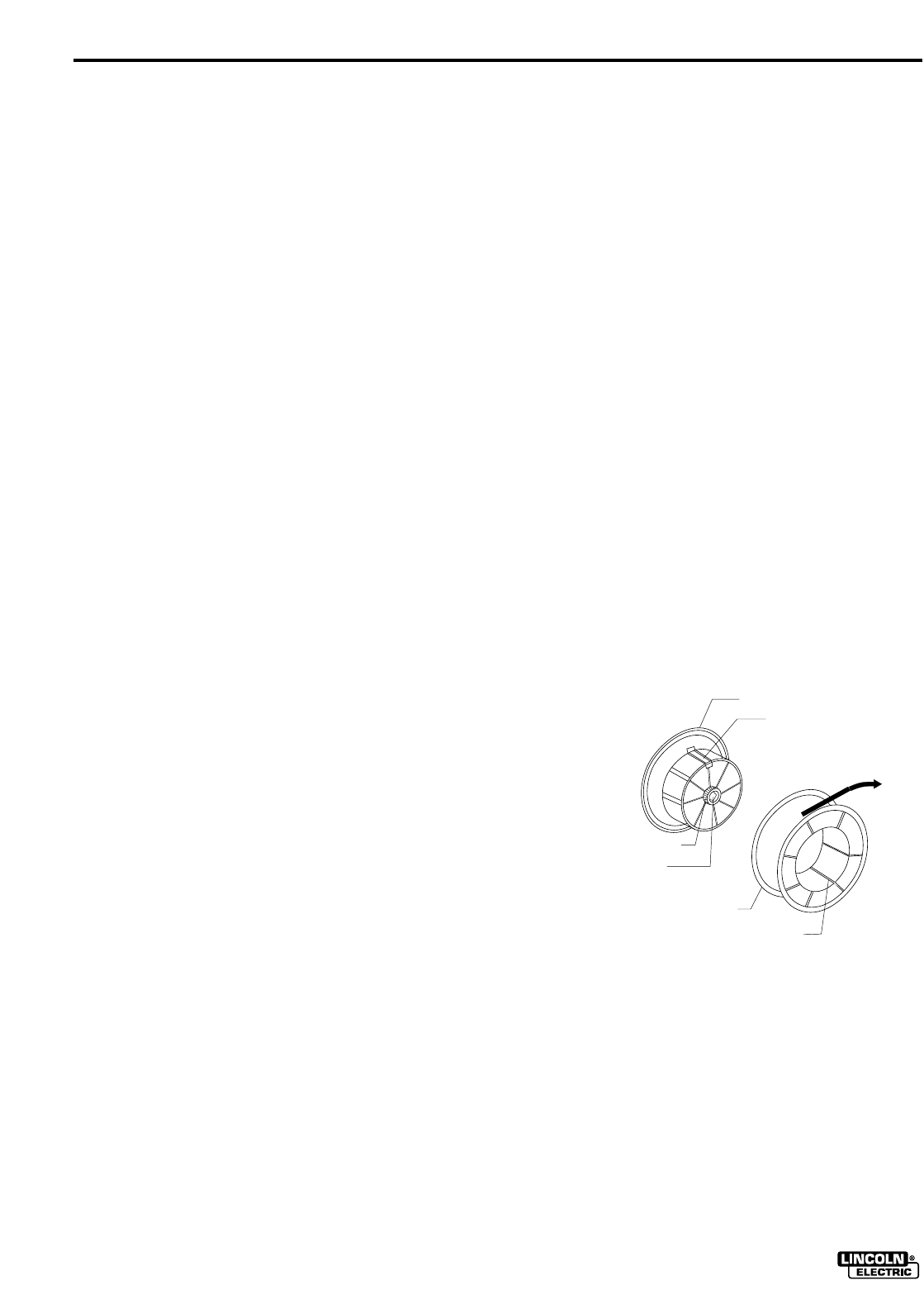
3. Position the Readi-Reel so that it will rotate in a
counterclockwise direction (as viewed from
retaining spring side of Adapter) when wire is
dereeled from the top of the coil as shown below:
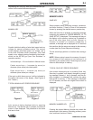
4. Set one of the Readi-Reel inside cage wires on the
slot in the retaining spring tab.
5. Lower the Readi-Reel to depress the retaining
spring and align the other inside cage wires with
the grooves in the molded adapter.
6. Slide cage all the way onto the adapter until the
retain spring “pops up” fully.
MOLDED ADAPTER
RETAINING SPRING
BRAKE TENSION
ADJUSTING SCREW
2" O.D. SPINDLE LOCKING COLLAR
READI-REEL
INSIDE CAGE WIRES
WIRE DEREELING
DIRECTION