


5
Foot
12
3
010173
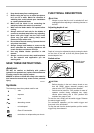
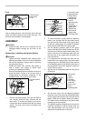
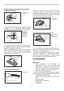
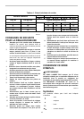
After a cutting operation, raise the back side of the tool
and a foot comes under the level of the rear base. This
prevents the tool blades to be damaged.
ASSEMBLY
CAUTION:
• Always be sure that the tool is switched off and
unplugged before carrying out any work on the
tool.
Removing or installing mini planer blades
CAUTION:
• Tighten the blade installation bolts carefully when
attaching the blades to the tool. A loose installation
bolt can be dangerous. Always check to see they
are tightened securely.
• Handle the blades very carefully. Use gloves or
rags to protect your fingers or hands when
removing or installing the blades.
• Use only the Makita wrench provided to remove or
install the blades. Failure to do so may result in
overtightening or insufficient tightening of the
installation bolts. This could cause an injury.
1
2
002564
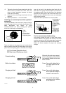
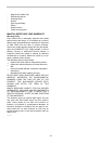
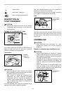
1. Remove the existing blade, if the tool has been in
use, carefully clean the drum surfaces and the
drum cover. To remove the blades on the drum,
unscrew the three installation bolts with the socket
wrench. The drum cover comes off together with
the blades.
1
2
3
4
5
6
7
8
9
10
002565
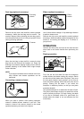
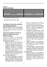
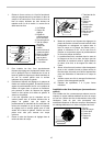
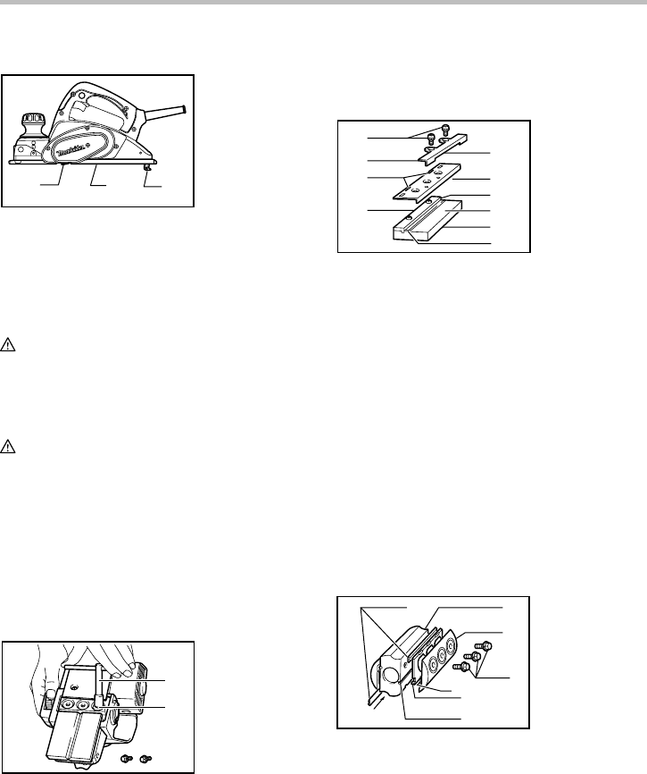
2. To install the blades, loosely attach the adjusting
plate to the set plate with the pan head screws
and set the mini planer blade on the gauge base
so that the cutting edge of the blade is perfectly
flush with the inside flank of the gauge plate.
3. Set the adjusting plate/set plate on the gauge
base so that the planer blade locating lugs on the
set plate rest in the mini planer blade groove, then
press in the heel of the adjusting plate flush with
the back side of the gauge base and tighten the
pan head screws.
4. It is important that the blade sits flush with the
inside flank of the gauge plate, the planer blade
locating lugs sit in the blade groove and the heel
of the adjusting plate is flush with the back side of
the gauge base. Check this alignment carefully to
ensure uniform cutting.
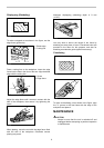
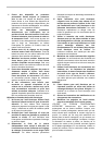
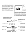
5. Slip the heel of the adjusting plate into the groove
of the drum.
1
2
3
4
5
6
7
002566
6. Set the drum cover over the adjusting plate/set
plate and screw in the three hex flange head bolts
so that a gap exists between the drum and the set
plate to slide the mini planer blade into position.
The blade will be positioned by the planer blade
locating lugs on the set plate.
7. The blade's lengthwise adjustment will need to be
manually positioned so that the blade ends are
clear and equidistant from the housing on one
side and the metal bracket on the other.
1. Mini planer
blade
2. Groove
3. Set plate
4. Hex. flange
head bolt
5. Drum cover
6. Drum
7. Adjusting plate
1. Pan head screw
2. Adjusting plate
3. Planer blade
locating lugs
4. Gauge plate
5. Heel of
adjusting plate
6. Set plate
7. Inside flank of
gauge plate
8. Gauge base
9. Back side of
gauge base
10.
Mini
p
laner blade
1. Socket wrench
2. Bolt
1. Planer blade
2. Rear base
3. Foot