


6
8. Tighten the three hex flange head bolts (with the
socket wrench provided) and hand rotate the
drum to check clearances between the blade
ends and the tool body.
9. Check the three hex flange head bolts for final
tightness.
10. Repeat procedures 1 - 9 for other blade.
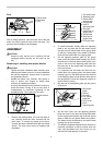
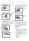
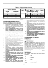
Installing conventional planer blade (optional
accessory)
To install the blades, first clean out all chips or foreign
matter adhering to the drum or blades. Use blades of the
same dimensions and weight, or drum
oscillation/vibration will result, causing poor planing
action and, eventually, tool breakdown.
1
2
3
4
5
002555
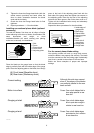
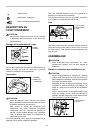
Place the blade on the gauge base so that the blade
edge is perfectly flush with the inside edge of the gauge
plate. Place the adjusting plate on the blade, then simply
press in the heel of the adjusting plate flush with the
back side of the gauge base and tighten two screws on
the adjusting plate. Now slip the heel of the adjusting
plate into the drum groove, then fit the drum cover on it.
Tighten all the installation bolts evenly and alternately
with the socket wrench.
Repeat the above procedures for the other blade.
1
2
3
4
5
6
7
8
9
002556
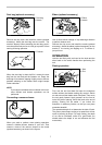
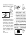
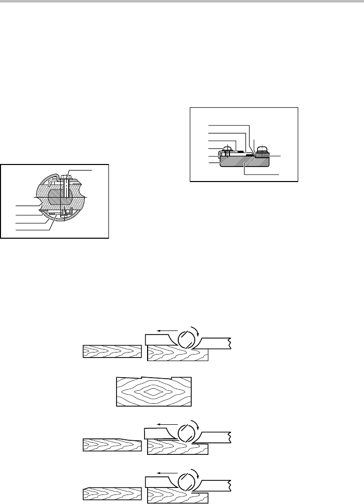
For the correct planer blade setting
Your planing surface will end up rough and uneven,
unless the blade is set properly and securely. The blade
must be mounted so that the cutting edge is absolutely
level, that is, parallel to the surface of the rear base.
Below are some examples of proper and improper
settings.
(A)
(B)
(B)
(A)
(B)
(A)
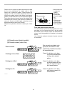
(A) Front base (Movable shoe)
(B) Rear base (Stationary shoe)
Correct setting
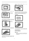
Nicks in surface
Gouging at start
Gouging at end
Although this side view cannot
show it, the edges of the blades
run perfectly parallel to the rear
base surface.
Cause: One or both blades fails to
have edge parallel to rear
base line.
Cause: One or both blade edges
fails to protrude enough in
relation to rear base line.
Cause: One or both blade edges
protrudes too far in relation
to rear base line.
EN0004-1
1. Inside edge of
gauge plate
2. Blade edge
3. Planer blade
4. Adjusting plate
5. Screws
6. Heel
7. Back side of
gauge base
8. Gauge plate
9. Gau
g
e base
1. Bolt
2. Drum
3. Planer blade
4. Drum cover
5. Adjusting plate