6
FUNCTIONAL
DESCRIPTION
CAUTION:
• Always be sure that the tool is switched off and
unplugged before adjusting or checking function on the
tool.
Depth adjustment
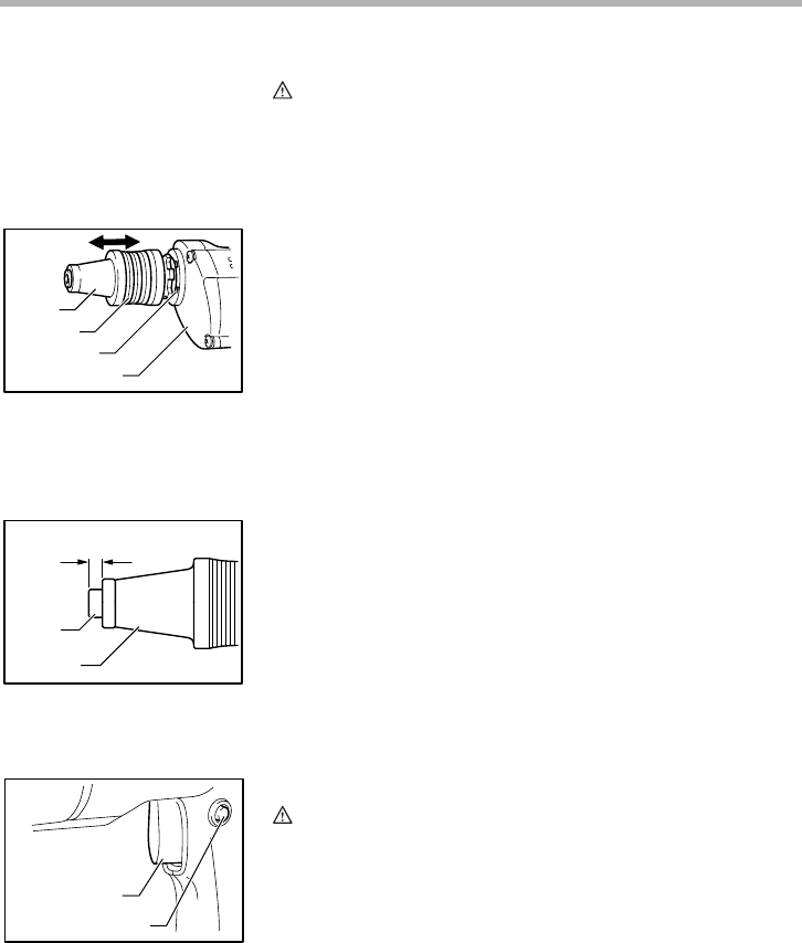
Pull the locking sleeve forward and then turn it to adjust the
depth. Initially, adjust the locator assembly to create a dis-
tance of approximately 0.5 mm from the tip of the locator to
the tip of the socket bit. One full turn of the locator equals
1.5 mm change in depth. After adjusting the locator assem-
bly, push the locking sleeve in to lock the locator in place.
Drive a trial screw into your material or a piece of duplicate
material. If the depth is not suitable for the screw, continue
adjusting until the proper depth setting is obtained.
Switch action
CAUTION:
• Before plugging in the tool, always check to see that the
switch trigger actuates properly and returns to the “OFF”
position when released.
To start the tool, simply pull the switch trigger. Tool speed is
increased by increasing pressure on the switch trigger.
Release the switch trigger to stop.
For continuous operation, pull the switch trigger and then
push in the lock button.
To stop the tool from the locked position, pull the switch trig-
ger fully, then release it.
1. Locator
2. Locking sleeve
3. Locking position
4. Gear housing
1. Socket bit
2. Locator
1
2
3
4
004146
1
2
0.5 mm
004151
1. Switch trigger
2. Lock button
1
2
004202


