


P 4/ 6
R
epair
[3] DISASSEMBLY/ASSEMBLY
[3]-2. Gear Ass’y and DC Motor (cont.)
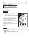
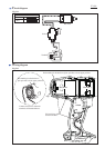
ASSEMBLING
Do the reverse of the disassembling steps.
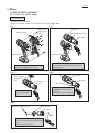
The following portions of DC motor, Motor bracket and Gear ass’y have to face the same side. (Fig. 7)
* Red point mark (designated as plus terminal) on DC Motor
* None of protrusion side of Motor bracket
* protrusion of Gear ass’y
Do not face the protrusion of
Motor bracket to the protrusion
of Gear ass’y and the red
point mark on DC motor.
Fig. 7
red point mark
on DC motor
Gear ass’y
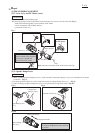
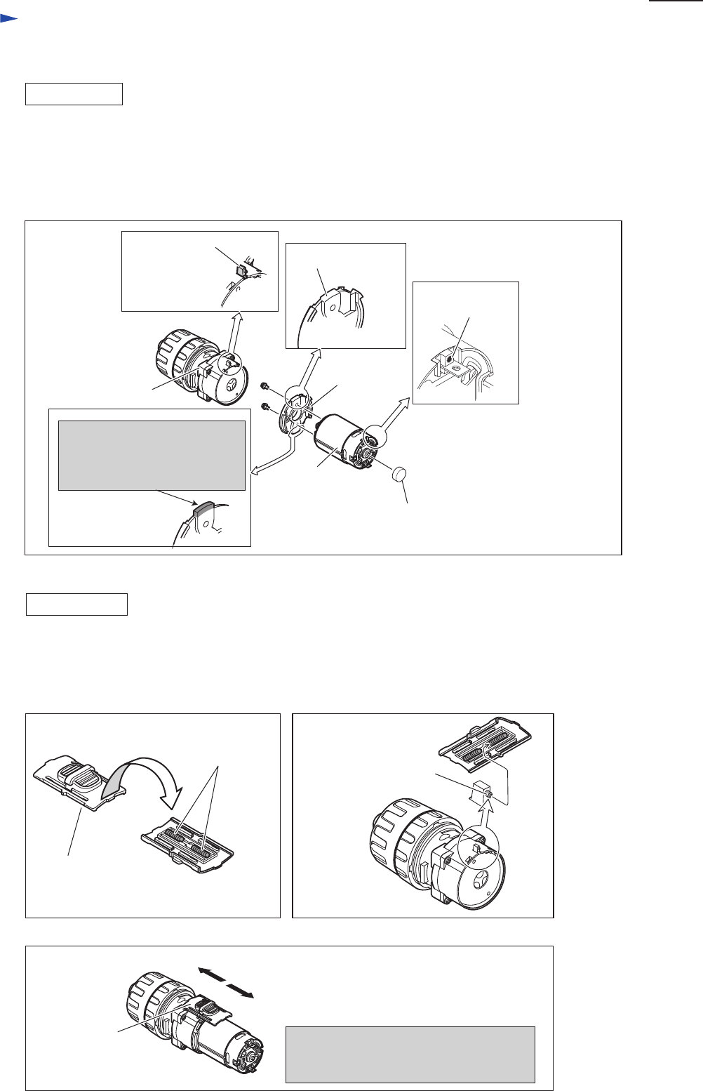
(1) When assembling Speed change lever ass’y, make sure that Compression springs 4 (2 pcs.) are assembled to its bottom
in advance. (Fig. 8)
(2) Fit the protrusion of Gear ass’y into Compression spring 4 in Speed change lever ass’y . (Fig. 9)
(3) After mounting, set Speed change lever ass’y to low speed mode or high speed mode. (Fig. 10)
Motor bracket
DC motor
Cap
Note : Be sure to Cover the center of DC motor with Cap.
none of protrusion
side
protrusion of Gear ass’y
[3]-3. Speed Change Lever
ASSEMBLING
Compression
spring 4 (2 pcs.)
Speed change lever
ass’y
protrusion of Gear ass’y
Fig. 8
Fig. 9
Fig. 10
Speed change
lever ass’y
Slide Speed change lever to either of
the direction designated in arrow, and hold
the position.
1: Low speed mode
2: High speed mode