


P 6/ 6
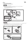
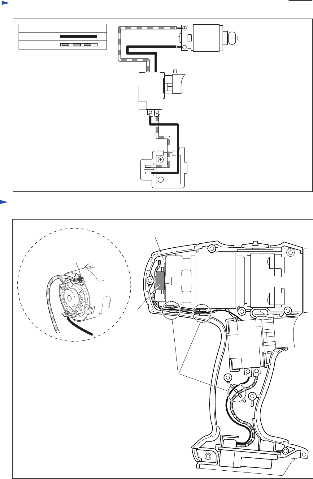
Wiring diagram
Fig. D-2
Red marking for distinction of
plus pole has to be at upper position.
Connect Lead wires with each
terminals as illustrated above.
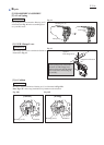
Circuit diagram
Fig. D-1
Color index of lead wire’s sheath
Black
Red
Switch
DC motor
Terminal
Red marking for distinction of plus pole has to be at upper position.
Fix lead wires with
lead wire holders.
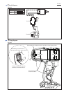
DC motor
Cap
Gear ass’y
Switch
Terminal