


13
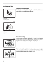
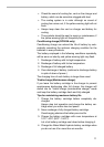
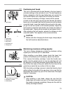
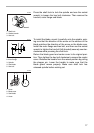
Positioning kerf board
This tool is provided with the kerf boards in the turn base to
minimize tearing on the exit side of a cut. The kerf boards are
factory adjusted so that the saw blade does not contact the
kerf boards. Before use, adjust the kerf boards as follows:
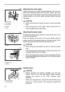
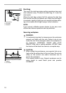
First, remove the battery cartridge. Loosen all the screws
(2 each on left and right) securing the kerf boards. Re-tighten
them only to the extent that the kerf boards can still be easily
moved by hand. Lower the handle fully and push in the stop-
per pin to lock the handle in the lowered position. Adjust the
kerf boards so that the kerf boards just contact the sides of
the blade teeth. Tighten all the screws (do not tighten firmly).
After adjusting the kerf boards, release the stopper pin and
raise the handle. Then tighten all the screws securely.
CAUTION:
• Before and after changing the bevel angle, always adjust
the kerf boards as described above.
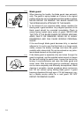
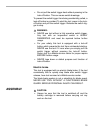
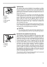
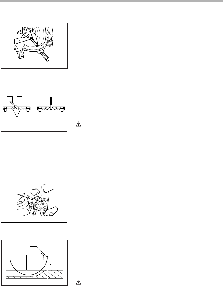
Maintaining maximum cutting capacity
This tool is factory adjusted to provide the maximum cutting
capacity for a 216 mm (8-1/2”) saw blade.
When installing a new blade, always check the lower limit
position of the blade and if necessary, adjust it as follows:
First, remove the battery cartridge. Lower the handle com-
pletely. Use the socket wrench to turn the adjusting bolt until
the periphery of the blade extends slightly below the top sur-
face of the turn base at the point where the front face of the
guide fence meets the top surface of the turn base.
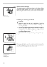
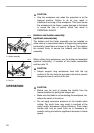
With the battery cartridge removed, rotate the blade by hand
while holding the handle all the way down to be sure that the
blade does not contact any part of the lower base. Re-adjust
slightly, if necessary.
CAUTION:
• After installing a new blade, always be sure that the
blade does not contact any part of the lower base when
the handle is lowered completely. Always do this with the
battery cartridge removed.
1. Kerf board
1. Saw blade
2. Blade teeth
3. Kerf board
4. Left bevel cut
5. Straight cut
1
001799
12
3
45
001800
1. Adjusting bolt
1. Top surface ot turn base
2. Periphery of blade
3. Guide fence
1
001801
2
1
3
001540