


P 6/ 15
Repair
[3] DISASSEMBLY/ASSEMBLY
[3] -2. Armature (cont.)
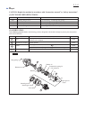
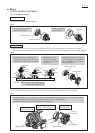
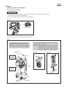
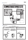
(3) Assemble Motor section (Armature, Yoke unit ), Internal gear case and Brush holder to Housing set (L) as drawn
in Fig. 8.
Fig. 8
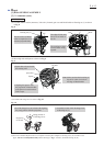
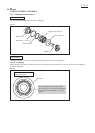
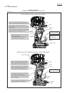
Fig. 9
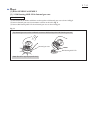
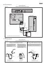
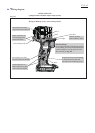
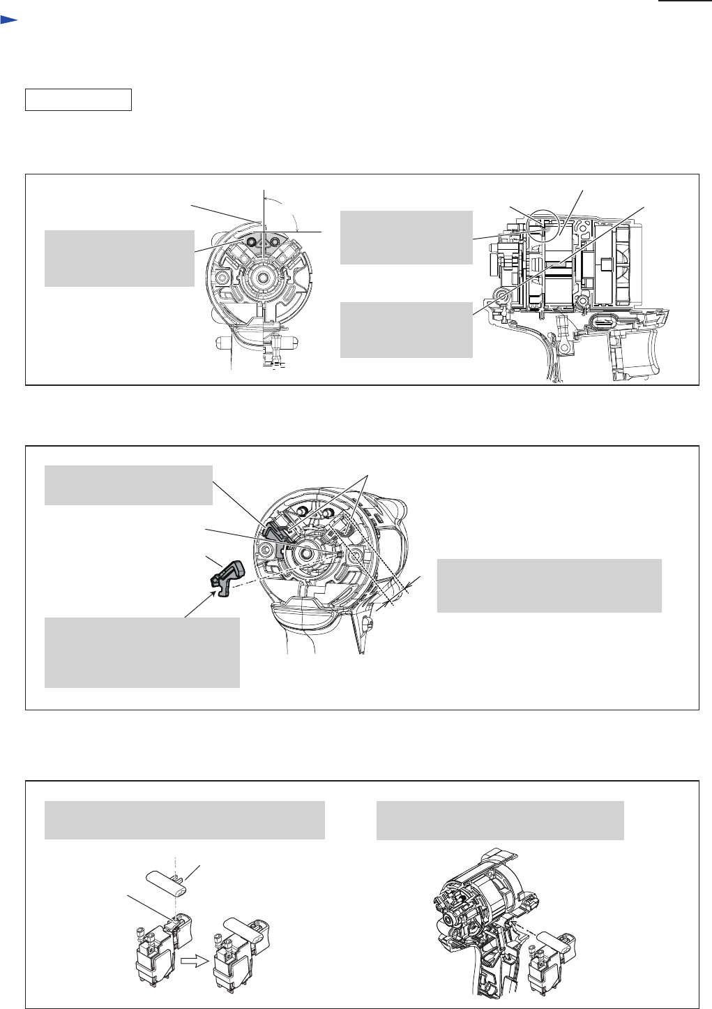
Fig. 10
ASSEMBLING
Rib
90°
Yoke unit
Mark
Housing Set (L)
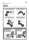
(5) Assemble F/R change lever as drawn in Fig. 10.
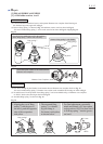
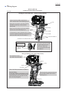
(6) Be sure to assemble ID plate and Cover complete or Switch plate complete to Housing set (L) in accordance with
[3] -1. Note for Assembly/Disassembly
and the drawings in Fig. 2. And then, assemble Housing set (R).
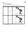
(4) Mount Pig tails and Spacers as drawn in Fig. 9.
2. Assemble Switch with F/R change lever
to Housing set (L).
Prong portion of
F/R change lever
Projection
of Switch
Pig tails
Note: Make sure that the loosening of
Pig tail is within 9 mm from
the edge of Brush holder.
1. Set F/R change lever to Switch with aligning
the prong portion with the projection.
projection
9mm
Spacer
2. Aligning this groove with
the projection of Brush holder,
push Spacer toward Armature
until it stops.
The flat surface of Brush
holder complete has to be
mounted perpendicularly.
The edge of Yoke unit
has to be set inside of
the rib.
The marking on Yoke
unit should be facing
upward.
1. Spacer has to be set inside
the housing wall.