


P 2/ 5
Repair
CAUTION: • Repair the machine in accordance with “Instruction manual” or “Safety instructions”.
• Due to the difference of factories, the shapes and positions of actual parts are different
from those shown in the following drawings.
[1] DISASSEMBLING / ASSEMBLING
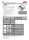
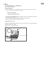
[1]-1. Charger case and Terminal unit
DISASSEMBLING
ASSEMBLING
Cap 13 (4pcs.)
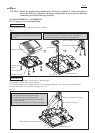
Remove Charger case and Terminal unit as drawn in Fig. 1.
1. Remove four Caps 13 and Tapping screws.
Charger case is separated from Charger case
cover.
2. Remove the connectors of Terminal unit from CN1 (connector 1)
and CN2 (connector 2) of Charging circuit. Then remove
Compression spring 4 from the boss of Terminal unit.
Tapping screw
(4pcs.)
Charger case
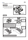
(1) Set Compression spring 4 to Terminal unit. Refer to Fig. 1.
(2) Assemble Terminal unit as drawn in Fig. 2.
(3) Assemble Charger case to Charger case cover by fastening four Tapping screws. Do not pinch the lead wires.
(4) Insert four Caps 13 into the holes of Charger case cover.
Fig. 1
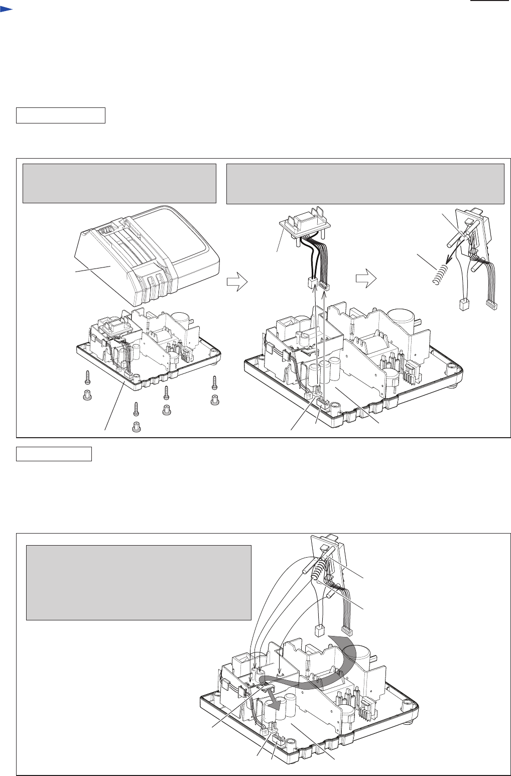
Fig. 2
CN 1
Charger case cover
CN 2
Charging circuit
Boss of Terminal unit
Terminal unit
Compression spring 4
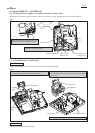
1. Pass the connectors of Terminal unit through
the notch and the hook of Terminal base.
2. Put the three legs of Terminal unit and
the end of Compression spring 4 into each hole
of Terminal base.
3. Connect the connectors with Circuit board. (Fig. 1.)
CN 1
Notch and hook of Terminal base
CN 2
Charging circuit
Legs of Terminal unit (3pcs.)
Compression spring 4