


Repair
[4] DISASSEMBLY/ASSEMBLY
[4]-6. Shaft pipe B complete
DISASSEMBLING
ASSEMBLING
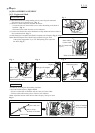
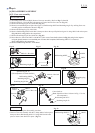
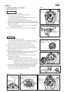
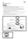
(1) Remove two M5x25 Hex socket head bolts and Pipe clamp 24 from Shaft pipe B complete.
Clamp cover A, Pipe clamp 33 and Loop handle are removed. (Fig. 24)
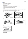
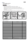
(2) Remove four 4x18 Tapping screws and two M5x14 Hex socket head bolts from Control lever assembly.
Control lever assembly is now separated to L and R. (Fig. 25)
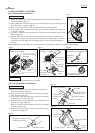
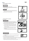
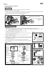
(3) Loosen M5x12 Hex socket head bolt and M6x25 Hex socket head bolt, and remove Joint 24 from Shaft pipe B complete.
(Fig. 26)
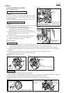
(4) Loosen M5x20 Pan head screw of Hanger set, and remove Hanger set itself and Spacer 24 from Shaft pipe B complete.
(Fig. 27)
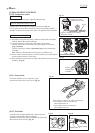
(5) Pull out Shaft B complete from the pipe joint side of Shaft pipe B complete. (Fig. 28)
Remove Retaining ring S-12.
*Loop handle
Assemble by reversing the disassembly procedure.
P 6/ 14
Fig. 24
Fig. 26
Fig. 28
Fig. 27
Fig. 25
*Clamp cover A
*Pipe clamp 33
M5x12 Hex socket
head bolt
*mark: The components of
Loop handle set
4x18 Tapping screw (4 pcs.)
M5x14 Hex socket head bolt (2 pcs.)
*Pipe clamp 24
*M5x25 Hex socket head bolt (2 pcs.)
Control lever assembly
Spacer 24
Hanger set
(Hanger and M5x20 Pan head screw)
M6x25 Hex socket
head bolt
Joint 24
Shaft B complete on Pipe joint side Shaft B complete on Engine side
Pipe joint side of Shaft pipe B complete
Retaining ring S-12
Joint end of Shaft B complete for installing
the tool head