


ADDITIONAL SAFETY RULES
1. Wear a hard hat (safety helmet), safety glasses
and/or face shield. It is also highly recom-
mended that you wear a dust mask, ear pro-
tectors and thickly padded gloves.
2. Be sure the bit is secured in place before
operation.
3. Under normal operation, the tool is designed
to produce vibration. The screws can come
loose easily, causing a breakdown or accident.
Check tightness of screws carefully before
operation.
4. In cold weather or when the tool has not been
used for a long time, let the tool warm up for
several minutes by operating it under no load.
This will loosen up the lubrication. Without
proper warm-up, hammering operation is dif-
ficult.
5. Always be sure you have a firm footing.
Be sure no one is below when using the tool in
high locations.
6. Hold the tool firmly with both hands.
7. Keep hands away from moving parts.
8. Do not leave the tool running. Operate the tool
only when hand-held.
9. Do not point the tool at any one in the area
when operating. The bit could fly out and
injure someone seriously.
10. When drilling or chipping into walls, floors or
wherever “live” electrical wires may be
encountered, DO NOT TOUCH ANY METAL
PARTS OF THE TOOL!
Hold the tool by the insulated grasping sur-
faces to prevent electric shock if you drill or
chip into a “live” wire.
11. Do not touch the bit or parts close to the bit
immediately after operation; they may be
extremely hot and could burn your skin.
SAVE THESE INSTRUCTIONS.
OPERATING INSTRUCTIONS
Bit grease
Coat the bit shank head beforehand with a small
amount (about 0.5–1g) of bit grease. This chuck
lubrication assures smooth action and longer service
life.
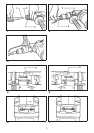
Installing or removing drill bit (Fig. 1)
Important:
Always be sure that the tool is switched off and
unplugged before installing or removing the bit.
To install the bit, press the change ring in the direction
of the arrow, align the key groove in the bit shank with
the red dot and insert the bit. Now release the change
ring. If the change ring does not return to its original
position easily, turn the bit slightly in either direction.
To remove the bit, press the change ring in the
direction of the arrow and the bit will slip out.
Adjusting depth of drilling (Fig. 2)
Loosen the wing bolt and adjust the depth gauge to
the desired depth. After adjusting, tighten the wing
bolt.
Side grip (auxiliary handle) (Fig. 3)
The side grip swings around to either side, allowing
easy handling of the tool in any position. Loosen the
side grip by turning it counterclockwise, swing it to the
desired position and then tighten it by turning clock-
wise.
Selecting action mode
For HR1820 (Fig.4&5)
Rotation with hammering:
For drilling in concrete, granite, tile, etc., press the
push rod in the
direction. (Fig. 4)
Rotation only:
For drilling in wood or metal, press the push rod in the
direction. (Fig. 5)
CAUTION:
To avoid rapid wear on the mode change mechanism,
be sure to press the push rod as far as it will go.
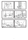
For HR2510 (Fig.6&7)
Rotation with hammering:
For drilling in concrete, granite, tile, etc., rotate the
change lever to the
position. (Fig. 6)
Rotation only:
For drilling in wood or metal, rotate the change lever
to the
position. (Fig. 7)
CAUTION:
To avoid rapid wear on the mode change mechanism,
be sure that the change lever is always positively
located in one of the two action mode positions.
Switch action (Fig. 8)
CAUTION:
•
Before plugging in the tool, always check to see that
the switch trigger actuates properly and returns to
the ‘‘OFF’’ position when released.
•
Do not tape, tie or otherwise secure the trigger in
the ‘‘ON’’ position.
To start the tool simply pull the trigger. Tool speed is
increased by increasing pressure on the trigger.
Release the trigger to stop. A speed control screw is
provided so that maximum tool speed can be limited
(variable). Turn the speed control screw clockwise for
higher speed, and counterclockwise for lower speed.
7