


Repair
P 9 / 22
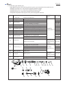
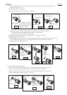
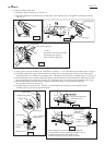
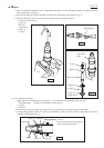
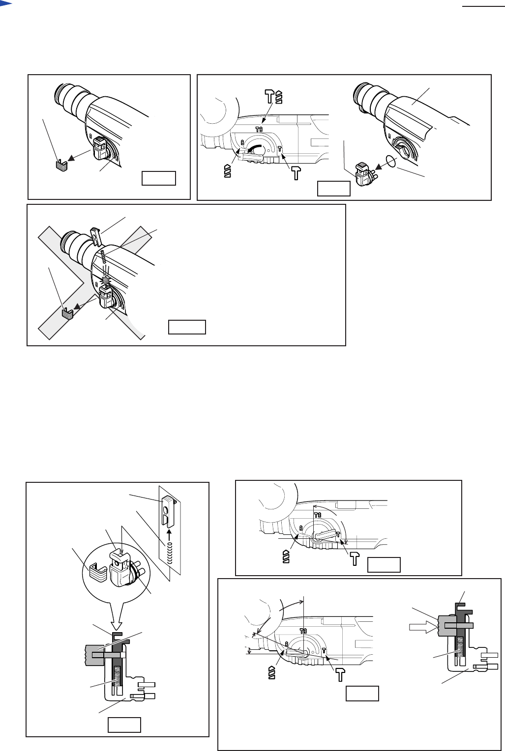
< 7 > Disassembling change lever
(1) Separate cap from change lever. See Fig. 35.
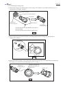
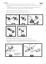
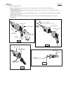
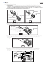
(1) Apply grease to the pin of change lever and O ring 17. Refer to "< 2 > Lubrication to the machine parts" in page 3.
< Note >
Be careful, not to lose lock button
and compression spring 3.
They can easily spring off.
(2) Fully turn change lever in the direction of drill mode. Then, change lever can be pulled out from gear housing.
See Fig. 36.
< 8 > Assembling change lever
Fig. 36
Fig. 37
Fig. 38
Fig. 39
Cap
Gear housing
Cap
Gear housing
Gear housing
Lock button
Compression spring 3
Fig. 35
Fig.36F
Change
lever
O ring 17
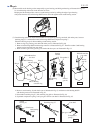
(2) Assemble compression spring 3 and lock button to change lever. And temporarily assemble cap to the position
illustrated in Fig. 37 in order to stop springing off of lock button. Do not forget to assemble O ring 17. See Fig. 37.
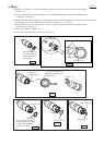
(3) Insert the change lever in which compression spring 3 and lock button have been temporarily fixed with cap, into
the assembling hole of gear housing. See Fig. 38. The change lever can not be inserted completely in this stage.
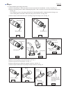
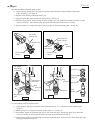
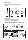
(4) Pressing the change lever, turn it in the direction of drill mode. Then, it can be inserted completely
in any position of area B. See Fig. 39.
(5) Turn the change lever to the area C. See Fig. 39. And assemble cap completely to the original position
of change lever, by pressing to gear housing side.
Cap
Change lever
Change lever
Change lever
Compression spring 3
Lock button
Cap, assembled
temporarily
Cap assembled
completely by
pressing.
Lock button
Lock button
Compression
spring 3
O ring 17
A
Insert the change lever
within the area A.
B
If the change lever can not be inserted completely
in any position of area B, pressing lock button, turn it
to the direction of drill mode again in order
to insert completely in any position of area B.
C
Compression
spring 3