


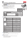
Repair
P 4/ 6
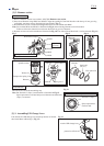
Take the reverse of the disassembling step.
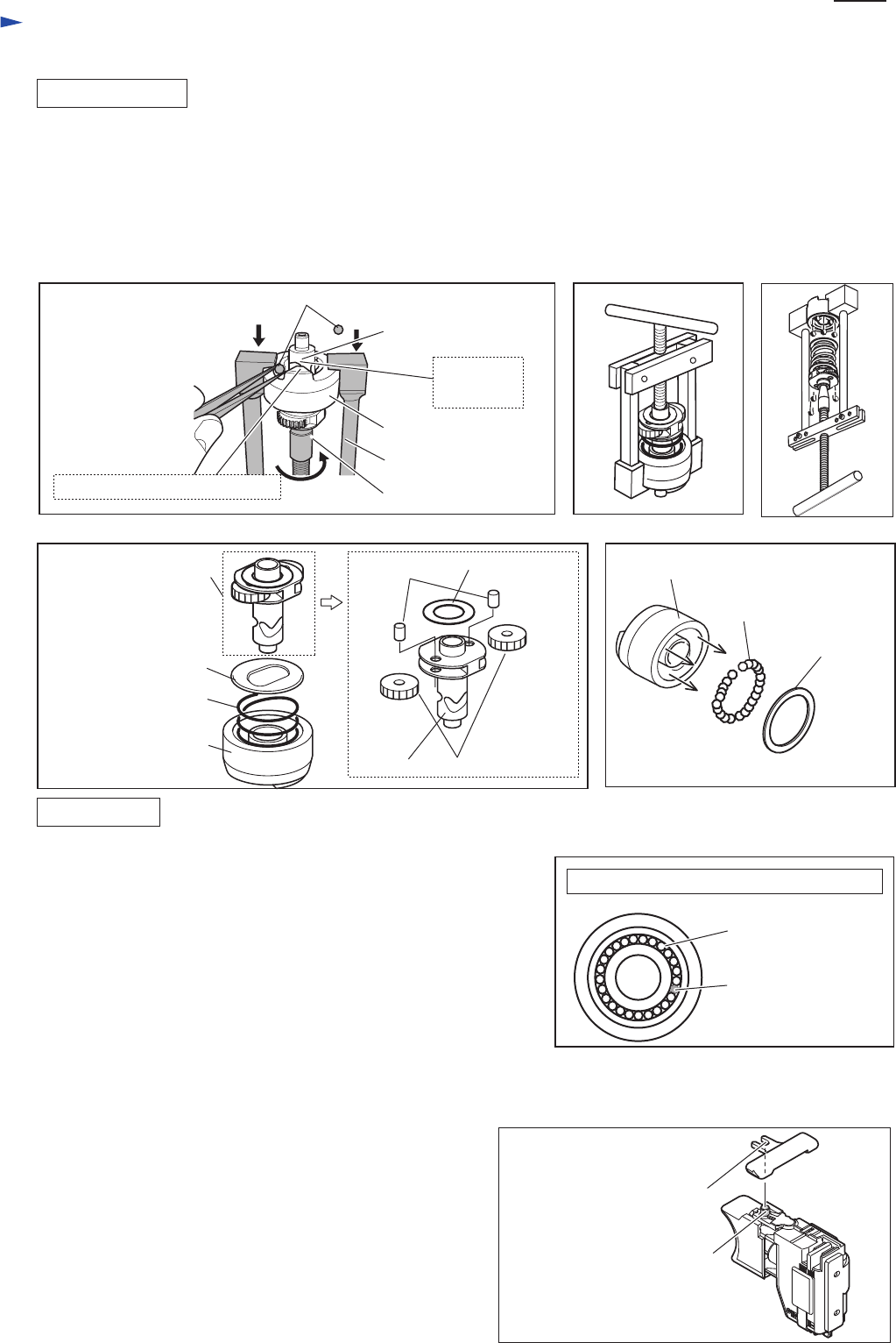
Note: Put Steel ball 3 (24pcs.) into Hammer as illustrated in Fig. 12.
Space equivalent to one Steel ball proves Hammer and Steel ball 3
(24pcs.) are normal.
[3]-3. Assembling F/R Change Lever
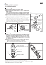
1) Remove Hammer section in accordance with [3]-1. Hammer case section.
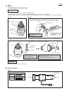
2) Press down Hammer using 1R045 and 1R346 to align the opening for Steel ball insertion with the top of cam grooving
on Spindle. And then, remove Steel ball 4.8 from Spindle. (Fig. 7)
3) Hold Hammer section as illustrated in Fig. 8 and release it from 1R346 and 1R045.
Note: Do not hold 1R346 and 1R045 as illustrated in Fig. 9 when releasing Hammer section from them.
Failure to follow this instruction could cause Steel balls to get out of hammer.
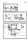
4) Hammer section can be disassembled as illustrated in Fig. 10. Flat washer 20 and Steel balls 3 can be removed. (Fig. 11)
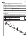
DISASSEMBLING
ASSEMBLING
[3]-2. Hammer section
Hammer
1R346
1R045
opening for Steel ball insertion
top of cam
grooving
Steel ball 4.8 (2pcs.)
Spindle
Fig. 9
Flat washer 12
Pin 3.5
Spindle Spur gear 17
Hammer
Flat washer 20
Compression spring 21
Washer 21
Steel ball 3
(24 pcs.)
Spindle section
Hammer
Fig. 7 Fig. 8
Fig. 10 Fig. 11
Fig. 12
Hammer viewed from Spindle insertion side
Steel ball 3 (24pcs.)
Space equivalent to
one Steel ball
Link the notch of F/R change lever and the protrusion of Switch,
then install them in Housing L. (Fig. 13)
Fig. 13
notch of F/R change lever
protrusion of Switch