


P 6/ 6
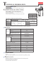
Wiring diagram
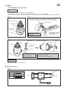
Fig. D-2
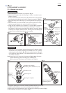
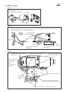
Fig. D-3
Pay attention to the directions of lead wires and connect Flag receptacles
to electrical parts.
Refer to the following illustration.
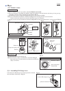
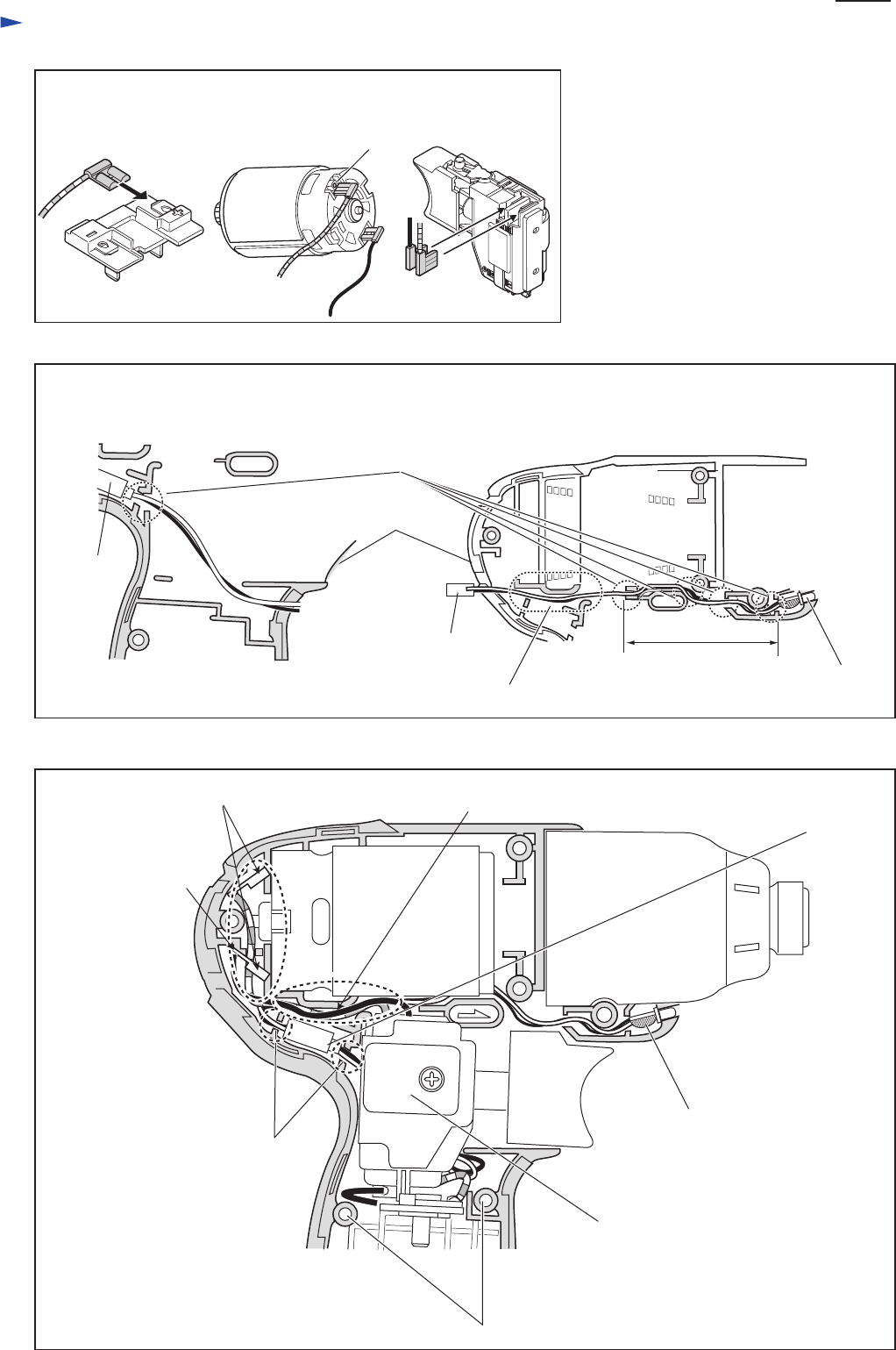
Fig. D-4
Before installing Switch in Housing R, route Lead wires as illustrated below and connect two Connectors.
Do not put their Lead wires on the ribs of Housing L.
Fix Lead wires
with Lead wire
holders.
Do not ride Lead wires on the screw embosses.
Terminal DC motor
Connector
Lead wire holders
Housing L
LED
Lead wires in this area
must be tight.
Lead wires have to fixed
with the ribs.
red marking
Connector
(To Switch)
Face the glue-attached portion of LED
downward.
Lead wires between Connector and
Switch have to be placed behind Switch.
Route Lead wires between ribs. Insert Connectors between
their Lead wire holders.
Bend the terminals of DC motor
as illustrated.
Flag receptacles and
Lead wires have to
be far from DC
motor.
Do not put them
on the ribs.