


USING THE AUDIO/VIDEO INPUT JACKS (CONTINUED)
FIXED
1
2
OUT
AUDIO
R
L
S-VIDEO
OUT
VIDEOOUT
Y
P
P
B
R
VIDEO 1
VIDEO 2
OUT
5
POSITION
DN
PIP
ANT A
AUX 1 DVD VIDEO
AUX 2 VIDEO
AUX 2 Y P
B
P
R
AUX 3 VIDEO
ANT B
AUX 1 DVD Y P
B
P
R
AUX 4 HD Y P
B
P
R
AUX 5 HD RGB-VGA
D1
D2
D3
D4
D5
D6
D7
D8
POWER
SOURCE
OFFON
ON/OFF
CLONE MACRO MODE
LE AR NIN G REMOT E CONT ROL
RC -1 8SR
MACRO
MACRO
1
2
3
4
OK
VOLCH
LD DVD
AUX
TAPE
CD
TV
TUNER
CD-R
/MD
DSS/
VCR2
VCR1
MUTE
GUIDEAMP
1
4
7
M
2
5
8
0
3
6
9
C
4
4
3
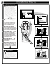
C
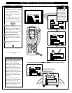
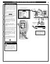
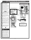
omponent Video Inputs
provide for the highest
possible color and picture
resolution in the playback of
digital signal source material such
as with DVD players. The color
difference signals (PB, PR) and the
luminance (Y) signal are
connected and received separately
which permits for improved color
bandwidth information (not
possible when using composite
video or S-Video connections).
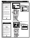
Connect the Component (Y PB
PR) VIDEO OUT jacks from the
DVD player to the (Y PB PR)
VIDEO IN(put) jacks on the TV.
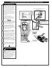
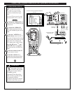
Connect the AUDIO OUT
jacks R(ight) and L(eft) from the
DVD player to the AUX 1 AUDIO
IN jacks on the TV.
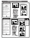
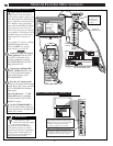
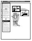
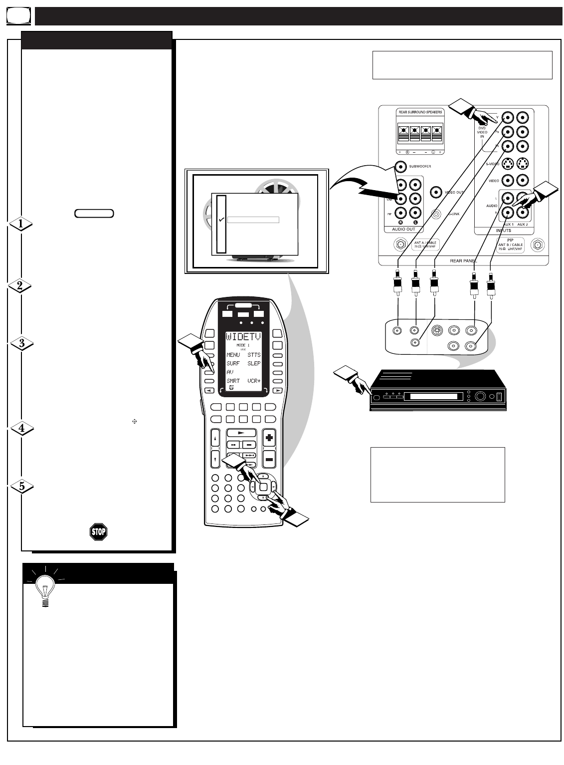
Select the "AUX 1 Y PB PR"
Picture Source control on the TV.
Press the A/V button on the remote
(or the Source Select button on the
front of the TV) to display the
TV’s Input Source control screen.
Press the OK arrow and
center OK
buttons to highlight
and select (
ߜ) the AUX 1 Y PB PR
mode.
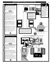
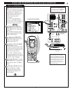
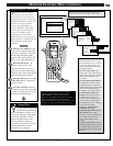
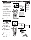
Turn the DVD player ON and
press PLAY to view the source
material playback on the TV.
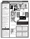
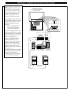
COMPONENT VIDEO INPUTS
COMPONENT
VIDEO OUTPUTS
AUDIO OUT (L/R)
(RED/WHITE)
Optional Video/Audio Cables (with standard
RCA plug connectors) are available to
complete your Component Input Jack
connections. Contact your dealer, or our Parts
Information Center (1-800-851-8885) to order
any optional accessories.
DVD PLAYER
(equipped with Component Color
& Luminance Outputs)
PICTURE AND SOUND FROM PLAYBACK
OF DVD SOURCE MATERIAL
BEGIN
SMART HELP
The description for the
component video connectors
may differ depending on the
DVD player or accessory digital source
equipment used (e.g. Y PB PR; R-Y/B-
Y/Y; Cr/Cb/Y, etc.). Although
abbreviations and terms may vary, the
letters “B” and “R” stand for the blue
and red color component signal
connectors, and “Y” indicates the
luminance signal. Refer to your DVD
or digital accessory Owner’s Manual
for definitions and connection details.
36
BACK OF TV
NOTE: Connections and use of the TV's rear AUX 2 Y P
B PR
Input jacks are the same as for the AUX 1 jacks (except
"AUX 2" Y PB PR is selected as the Picture Source in step 3).