


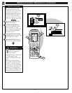

MONITOR FEATURES MENU CONTROLS
VOL
MENU
CH
STATUS/EXIT
GND
FM
AM
ANTENNA
VIDEO
DSS
LD VCR 2 IN-VCR-OUT
TV
MONT
MULTI REMOTE
IN
OUT
AC-3 RF
AC-3/
PCM
COAX
AC-3/PCM
OPT
IN
IN
L
R
CD
IN-TAPE-OUT DSS
LD
VCR 2
IN-VCR-OUT
MULTI
ON
OFF
1
USB
2
TV
RGB
SVGA
(RGB)
TV/CABLE
ANT
R DATA
IR
LINE
MIC
LINE IN
PHONE
SUB
WOOFER
CENTER
CENTERSURROUNDFRONT
L
R
AUDIO OUTPUT
L
1
2
PIP
ANT A
AUX 1 DVD VIDEO
AUX 2 VIDEO
AUX 2 Y P
B
P
R
AUX 3 VIDEO
ANT B
AUX 1 DVD Y P
B
P
R
AUX 4 HD Y P
B
P
R
AUX 5 HD RGB-VGA
D1
D2
D3
D4
D5
D6
D7
D8
POWER
SOURCE
OFFON
ON/OFF
CLONE MACRO MODE
LE AR NIN G REM OTE C ONT ROL
RC -1 8SR
MACRO
MACRO
1
2
3
4
OK
VOLCH
LD DVD
AUX
TAPE
CD
TV
TUNER
CD-R
/MD
DSS/
VCR2
VCR1
MUTE
GUIDEAMP
1
4
7
M
2
5
8
0
3
6
9
C
3
3
3
VGA/RGB/HDCOMPONENT
38
BRIGHTNESS
PICTURE
SHARPNESS
SVM OFF
COLOR
TINT
VOLUME BARON
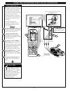
A
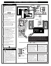
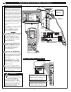
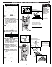
nother function with your TV
is for the connection and use
of Personal Computers (PCs), and
other High Definition (HD) digital
source equipment (through the use
TV’s Monitor inputs and display
mode). Dedicated HD Audio Input
jacks (located on the rear of the
TV) are also paired to the external
source Monitor Video Inputs (VGA
and HD Component Video In) for
audio playback connections as
well.
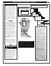
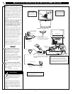
For example: To connect a Philips
DVX8000 Multimedia Home
Theater (MMHT) for monitor
mode display use on the TV:
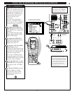
Connect a 15 pin VGA signal
cable (optional) from the VGA
(or SVGA) jack on the select
auxiliary equipment (example:
DVX8000 MMHT) to the VGA
Input jack on the TV.
Connect the Left/Right HD
INPUT AUDIO IN jacks on the
TV to the (L/R) Audio Output
jacks (labeled Front) on the
DVX8000 MMHT.
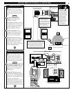
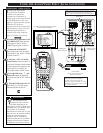
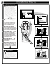
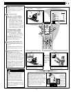
Press the A/V button on the
remote (or the Source Select button
on the front of the TV) to select the
AUX 5 HD RGB/VGA Monitor
Input mode.
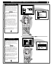
Press the OK arrow and
center OK
buttons to highlight
and select (
ߜ) the AUX 5 HD
RGB/VGA mode.
Use the DVX8000 MMHT as
the video (and/or audio) playback
source for material to be displayed
on the TV’s screen.
BEGIN
REAR OF TV
REAR OF DVX8000 MMHT
15 PIN VGA
Connection Cable
Left/Right
Audio IN
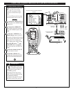
HD COMPONENT VIDEO IN
R
L
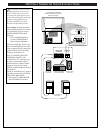
• Separate Red/Green/Blue (Luminance-Y and
Color Difference-Pr/Pb) Component Video
Inputs provide for improved color bandwidth
information and highest possible picture
resolution for digital source connections.
• H/H + V (for combined Horizontal/Vertical
sync signals) or V(ertical) sync inputs control
the display of a RBG sourced picture in the left-
to-right dimension and from top-to-bottom.
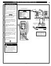
Note: The TV will
display any Television
compatible VGA or
SVGA (60Hz only)
signal input.
SMART HELP
Note: The TV’s video
display may temporarily appear
misconverged during the
initialization of certain VGA input
connected PC programs (i.e., DOS).
Once the PC program has completed its
“bootup” phase, normal signal level
processing will reoccur and the TV
display will return to normal.
REAR OF TV