


ENGLISH
15
ENG
The machine is also available with different acces-
sory parts. An overview can be found on page 4.
Subject to change.
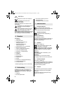
A Battery pack
B Nylon web compact disk
C File for profiling nylon web compact disks
D Sanding paper strips for file
7.1 Attaching the additional handle
Always work with the additional handle
attached (4)! Attach the additional handle on
the left or right of the machine and secure.
7.2 Attaching the hand guard
Always work with the hand guard (1)
attached.
To rotate hand guard (if required):
See illustration c, page 3.
Extract the screws (16), remove the hand
guard (1) and replace it so it is turned. Secure
with screws (16).
7.3 Dust filter
See illustration c on page 3.
Always fit the dust filter if the surroundings
are heavily polluted (11).
The machine heats up faster when the dust
filter is fitted (11). It is protected by the elec-
tronics system from overheating (see chapter11).
To fit:
See fig. page 3. Attach the dust filter (11) as
shown.
To remove:
Holding the dust filter at the edges, raise it slightly
(11) and then pull it downwards and remove.
7.4 Rotating battery pack
See illustration c on page 3.
The rear section of the machine can be rotated
270° in three stages, thus allowing the machine's
shape to be adapted to the working conditions.
Only operate the machine when it is in an engaged
position.
7.5 Battery pack
Charge the battery pack before use (10).
If performance diminishes, recharge the battery
pack.
The ideal storage temperature is between 10°C
and 40°C.
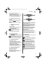
"Li-Power" li-ion battery packs have a capacity
and signal indicator: (9)
- Press the button (8), the LEDs indicate the
charge level.
- If one LED is flashing, the battery pack is almost
flat and must be recharged.
7.6 Removing and inserting the battery
pack
Removal:
Press the battery pack release (7) button and pull
the battery pack (10) forwards.
Inserting:
Slide in the battery pack (10) until it engages.
7.7 Twist the extension arm, if necessary.
- Slacken the screw (3).
- Twist the extension arm (2) (but not so far that it
hits the gearbox housing).
The extension arm must be fitted as far as
the limit stop on the gearbox flange.
Firmly tighten the screw (3) again.
Before carrying out any modifications:
remove the battery pack from the machine.
The machine must be switched off and the spindle
at a standstill.
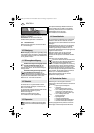
8.1 Positioning the accessory
See illustration c, page 3.
- The two sides of the support flange (14) are
different: Place the support flange (14) around
the spindle (15) in such a way that the large collar
diameter which corresponds to the accessory
(13) is facing upwards.
- Place the accessory (13) on the support flange
(14). The accessory must lay flat on the
supporting flange.
6 Scope of delivery
7 Initial Operation
8 Attaching the accessory
17027055_0411 KNS 18 LTX 150.book Seite 15 Dienstag, 26. April 2011 2:46 14