CABLE SPECIFICATIONS
Fiber Cable
Bit error rate: ≤10-9
MULTIMODE
Fiber Optic Cable Recommended: 62.5 / 125 µm multimode fiber
Optional: 100 / 140 µm multimode fiber
85 / 125 µm multimode fiber
50 / 125 µm multimode fiber
T1E1-CF-01 850 nM
Fiber Optic Transmitter Power: min: -14.0 dBm max: -12.0 dBm
Fiber Optic Receiver Sensitivity: min: -25.0 dBm max: -12.0 dBm
Typical Maximum Cable Distance*: 2 kilometers
T1E1-CF-01(SC) 850 nM
Fiber-optic Transmitter Power: min: -14.0 dBm max: -12.0 dBm
Fiber-optic Receiver Sensitivity: min: -25.0 dBm max: -12.0 dBm
Typical Maximum Cable Distance*: 2 kilometers
SINGLEMODE
Fiber Optic Cable Recommended: 9 µm singlemode fiber
T1E1-CF-01(SM) 1300 nM
Fiber-optic Transmitter Power: min: -21.0 dBm max: -14.0 dBm
Fiber-optic Receiver Sensitivity: min: -25.0 dBm max: -14.0 dBm
Typical Maximum Cable Distance*: 8 kilometers
T1E1-CF-01(LH) 1300 nM
Fiber-optic Transmitter Power: min: -15.0 dBm max: -5.0 dBm
Fiber-optic Receiver Sensitivity: min: -25.0 dBm max: -14.0 dBm
Typical Maximum Cable Distance*: 15 kilometers
*Actual distance dependent upon physical characteristics of network installation.
Twisted-Pair Copper Cable
Twisted pair connection requires two active pairs. The two active pairs in a T1/E1
network are pins 1 & 2 and pins 4 & 5. Use only dedicated wire pairs (such as
blue/white & white/blue) for the active pins.
Category 3 or better twisted-pair copper wire is required. Either shielded twisted-
pair (STP) or unshielded twisted-pair (UTP) can be used.
T1:
Gauge 24 to 22 AWG
Attenuation 2.6 dB/100 meters @ 1.0 MHz
Differential Characteristic Impedance 100 Ω ±10%
E1:
Gauge 24 to 22 AWG
Attenuation 2.6 dB/100 meters @ 1.0 MHz
Differential Characteristic Impedance 120 Ω ±10%
Coax Copper Cable
E1:
Gauge 24 to 22 AWG
Attenuation 2 dB/100 meters @ 1.0 MHz
Differential Characteristic Impedance 75 Ω ±10%
å
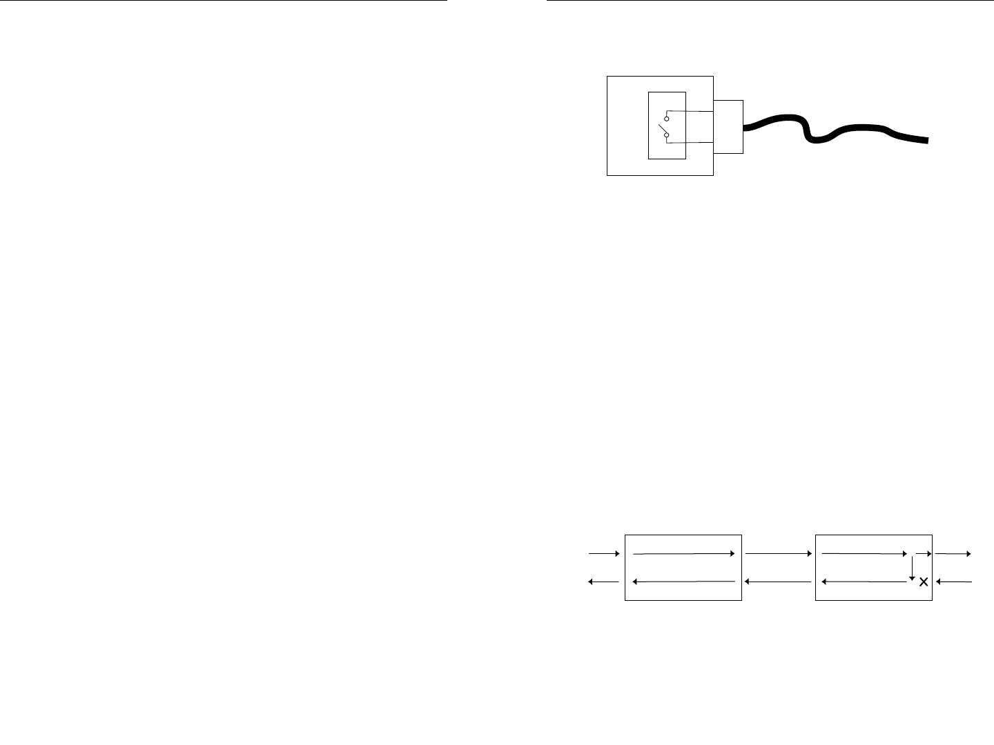
Dry-Contact Relay
RJ-45 dry-contact relay opens if power, signal detect/copper or signal
detect/fiber are lost.
Operational rating on pins 3 and 6: 0-30VDC maximum 1A
Switch-Selectable Configurations
T1 COPPER RJ-45
Configured as either "long haul" or “short haul” on 100 ohm cable, with
a variety of selectable distance settings.
E1 COPPER RJ-45
Configured as either "long haul" or “short haul” on 120 ohm cable.
E1 COPPER COAX
Configured as either "long haul" or “short haul” on 75 ohm cable.
STRAIGHT-THROUGH/CROSSOVER RJ-45
Allows straight-through cable to be used where crossover-configuration
cable is required.
Switch-Selectable Functions
LOOPBACK TEST FUNCTION
A loopback switch facilitates installation and network debug procedures.
The path for the T1E1-CF-01 loopback is shown:
TRANSMIT ALL ONES FUNCTION
A selectable Transmit All Ones switch on the fiber interface and on the
twisted-pair interface allows for insertion of an “all ones” pattern on that
interface when signal detect is lost, which creates an alarm condition at
the equipment connected to the interface.
Fiber
TP
TP
RJ-45
Relay
3
6


