


OM-2219 Page 11
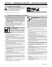
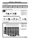
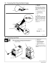
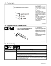
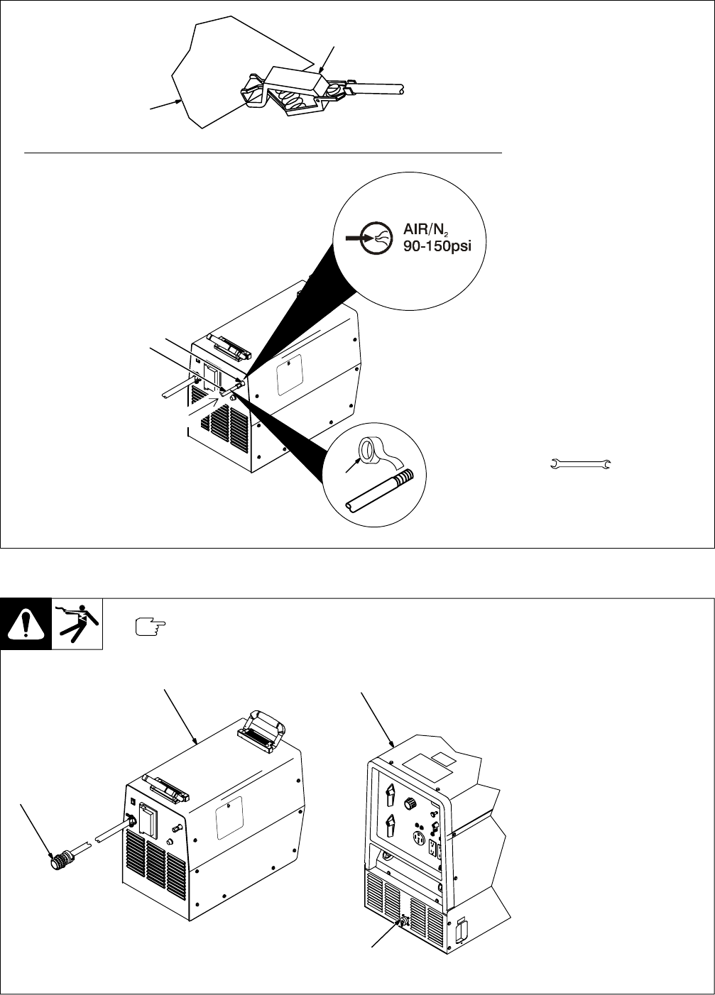
2-5. Connecting Work Clamp And Gas/Air Supply
Ref. 801 977-A
1 Work Clamp
2 Workpiece
Work clamp cable is attached to
front of unit. Connect work clamp to
a clean, paint-free location on work-
piece, as close to cutting area as
possible.
. Use only clean, dry air with 90
to 150 psi pressure.
3 Gas/Air Inlet Opening
4 Hose
5 Teflon Tape
Obtain hose with 1/4 NPT right-
hand thread fitting. Wrap threads
with teflon tape (optional) or apply
pipe sealant, and install fitting in
opening. Route hose to gas/air
supply.
Adjust gas/air pressure according
to Section 3-2.
Tools Needed:
5/8, 1-1/8 in
3
1
2
4
5
From Gas/Air Supply
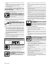
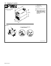
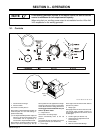
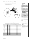
2-6. Connecting Input Power
Do not attempt to connect this unit to anything other than a
Miller engine-driven welding generator with the proper
receptacle installed.
1 Spectrum Lynx
2 Power Plug
3 Engine-Driven Welding
Generator With Required
Receptacle Installed
4 AC Power Receptacle For
Lynx
Connect power plug to proper re-
ceptacle on engine-driven welding
generator.
1
801 977-A / Ref. ST-802 200
Rear of Unit
2
3
4
Example Welding
Generator