


OM-2219 Page 12
SECTION 3 – OPERATION
If the welding generator includes a fine adjust control, be sure to set the
control to maximum for full output control capacity.
When using the Lynx, auxiliary power output is not available from the 120 or 240
VAC receptacles on the welding generator.
NOTE
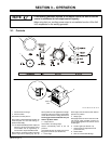
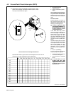
3-1. Controls
Ref. ST-189 734 / Ref. 801 977–A
6
1
2
4
5
7
Rear of
Unit
8
1 Gas/Air Pressure Gauge
2 Pilot Arc Switch
Use switch to control pilot arc.
Place switch in Expanded Metal position for
continuous pilot arc. Use while cutting ex-
panded metals only.
. The Expanded Metal position keeps the
pilot arc in the circuit at all times. Life of
consumables will be significantly re-
duced while in Expanded Metal mode.
Place switch in Tip Saver position to provide
pilot arc output for arc starting only. Use Tip
Saver position in most applications to length-
en the life of the torch and its consumables,
and to obtain maximum cutting performance.
Torch trigger must be reset after every cut
while in Tip Saver mode.
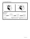
3 Output Control
Use control to set cutting output.
Gas/air automatically flows at the set
pressure.
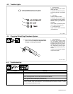
Use Gas/Air Set area of control range for set-
ting gas/air pressure (see Section 3-2).
4 Power Light
Power light comes On when Power switch is
placed in On position.
5 Ready Light
Ready light comes On when unit is On to indi-
cate that all safety shutdown systems are
okay. If Ready light does not come On, check
trouble lights.
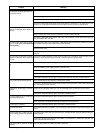
6 Trouble Lights (see Section 4-3)
7 Gas/Air Pressure Adjustment Knob
(see Section 3-2)
8 Power Switch
9 Door for Consumables Storage
9
3