


OM-223 194 Page 13
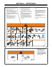
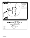
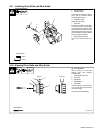
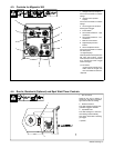
3-9. Installing Drive Rolls and Wire Guide
1 Securing Screw
2 Inlet Wire Guide
Loosen screw. Slide tip as close to
drive rolls as possible without
touching. Tighten screw.
3 Anti-Wear Guide
Install guide as shown.
4 Drive Roll
The drive roll consists of two differ-
ent sized grooves. The stamped
markings on the end surface of the
drive roll refers to the groove on the
opposite side of the drive roll. The
groove closest to the motor shaft is
the proper groove to thread.
5 Drive Roll Securing Nut.
Turn nut one click to secure drive
roll.
Tools Needed:
5/64 in
7/16 in
1
3
2
4
5
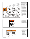
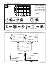
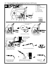
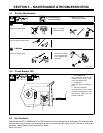
3-10. Aligning Drive Rolls and Wire Guide
Y Turn Off power.
View is from top of drive rolls
looking down with pressure
assembly open.
1 Drive Roll Securing Nut
2 Drive Roll
3 Wire Guide
4 Welding Wire
5 Drive Gear
Insert screwdriver, and turn screw
in or out until drive roll groove lines
up with wire guide.
Close pressure roll assembly.
Ref. 800 412-A
Correct Incorrect
4
3
2
1
5
Tools Needed: