


OM-223 194 Page 16
SECTION 4 − OPERATION
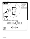
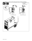
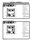
4-1. Controls for Migmatic 271/273
1
2
3
4
5
6
7
8
1 Voltage Control
Turn control clockwise to increase
voltage.
2 2T/4T Trigger Hold Function
Latching Torch Trigger
3 Power Switch
4 Work Lead Connection
5 MIG Torch Connection
6 Digital Display Function
Button*
7 Wire Feed Speed Control
Turn control clockwise to increase
wire feed speed.
8 Digital Display*
Volts/Amps/Wire Feed Speed with
last value hold function. Trigger
mode (2T/4T) is shown at power on
for 3 seconds and when Trigger
mode is changed.
. Not shown:
Jog and Purge controls are lo-
cated under the hinged side
wire consumable access door.
* Optional
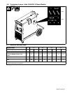
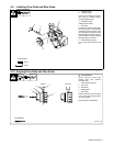
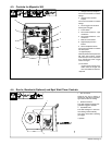
4-2. Controls for Migmatic 293/333
1
2
3
4
6
7
8
9
5
1 Voltage Control (Fine Adjust)
Turn control clockwise to increase
voltage.
2 Voltage Control (Coarse
Adjust)
Turn control clockwise to increase
voltage.
3 2T/4T Trigger Hold Function
Latching Torch Trigger
4 Power Switch
5 Work Lead Connection
6 MIG Torch Connection
7 Digital Display Function
Button*
8 Wire Feed Speed Control
Turn control clockwise to increase
wire feed speed.
9 Digital Display*
Volts/Amps/Wire Feed Speed with
last value hold function. Trigger
mode (2T/4T) is shown at power on
for 3 seconds and when Trigger
mode is changed.
. Not shown:
Jog and Purge controls are lo-
cated under the hinged side
wire consumable access door.
* Optional
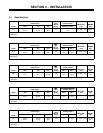
6 in