


OM-222 394 Page 22
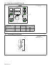
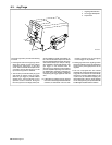
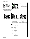
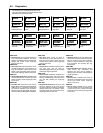
6-8. Feeder Set Up Push Button
1 Feeder Set Up Push Button LED
2 Feeder Set Up Push Button
• Press button to choose Sequence. Feeder
Set Up push-button LED will illuminate.
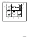
3 Sequence LED
• When the Feeder Set Up button is pressed
once, the Sequence LED will illuminate and
the upper display will show sequence
options. Use the Adjust knob to select PRE
(preflow), STRT (start), CRTR (crater), or
POST (postflow).
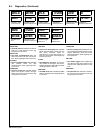
• Press the lower display push button and the
Lower Display push-button LED will
illuminate as well as the lower display. The
Time LED will automatically begin flashing
indicating that a time value can be entered
by turning the Adjust knob. By entering a
time value the sequence state will become
active. To turn off a sequence state, change
the time value to OFF. To step back for
selecting another sequence option, press
the Upper Display push button.
• The Sequence option STRT and CRTR will
have additional parameter settings. By
pushing the Lower Display push button a
second time, while STRT or CRTR appear
in the upper display, allows entering voltage
(MIG) or Arc Adjust [Pulse, Accu-pulse, or
RMD (optional)]. Use the Adjust knob to
change the values indicated by the flashing
LED for either Volts or Arc Adjust. Pressing
the Lower Display push button a third time
will activate the WFS setting for either STRT
or CRTR and the WFS LED will begin flash-
ing. Use the Adjust knob to change the WFS
value.
• Pressing the Feeder Set Up button two
more times will exit the Sequence menu and
return the system to standby mode.
4 Trigger Control LED
• Press the Feeder Set Up button twice and
the Trigger Control LED will illuminate, and
the upper display will show the different trig-
ger control selections. Use the Adjust knob
to cycle through the trigger control methods
as follows: DS, TH, TDS, TPS, and 4T (see
Section 5-1 for definitions). The lower dis-
play will show the current state of each trig-
ger control method as being on or off. Not all
trigger control methods are compatible with
each other, therefore, turning on certain trig-
ger selections will cause other trigger selec-
tions to turn off.
• Press the lower display push button to illu-
minate the push-button LED and enable the
use of the Adjust knob to allow turning se-
lected trigger control methods on or off. If
trigger hold is set to on, the Trigger Hold
LED will illuminate.
. Trigger Hold is automatically set to On
with the 4T trigger selection. This is part
of the 4T function.
• Press the Feeder Set Up button a third time
to cycle back to standby mode.
1
3
4
Trigger Control
Feeder Set Up
Trigger Hold
Sequence
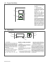
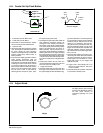
Sequence Diagram
Preflow
Time
Start
Time
Crater
Time
Postflow
Time
2
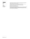
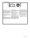
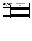
6-9. Adjust Knob
Adjust
1
1 Adjust Knob
The Adjust knob is used to change
functions and parameters. Refer to
the front panel sections for
information regarding use of this
control.