


OM-222 394 Page 23
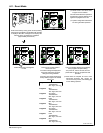
6-10. Process Set Up Push Button
• Press the Process Set Up push button the
first time will illuminate the button LED and
the Process LED. The upper and lower
displays will be used for Accu-pulse and
only the lower display for MIG, Pulse and
RMD (optional) to show the current process
installed in this program. To change
process, turn the adjust knob.
• Pressing the Process Set Up push button a
second time will illuminate the Wire Type
LED and the lower display will show wire
types available for selected processes (see
Table 6-1 for wire abbreviation). To make a
selection, turn the Adjust knob.
• Pressing the Process Set Up push button a
third time will keep Wire Type LED lit and the
upper display will show wire alloy type (see
Table 6-1 for alloy types). The upper display
push-button LED will be flashing indicating
that turning the Adjust knob will change the
alloy type for the selected process and wire
type.
• Pressing the Process Set Up push button a
fourth time will keep Wire Type LED lit and
the upper display will show wire size. The
upper display push button will be flashing
indicating that turning the Adjust knob will
select wire sizes available for that particular
process and wire type.
• Pressing the Process Set Up push button a
fifth time will illuminate the Gas Type LED
and the lower display will show GAS and the
upper display will show gas selection (see
Table 6-1 for gas abbreviations). To make a
gas type selection, turn the Adjust knob.
• If any of the Process, wire type, alloy type,
wire size, or gas type was changed, then
pressing the Process Set Up push button a
sixth time will show PROG in the upper
display and LOAD in the lower display. The
new program would be loaded for that
particular program in slot 1 thru 8. If no
changes were made to any setup items, no
program will be loaded, and unit will return
to standby mode.
• If a custom program is loaded using an
optional PDA with File Management/Wa-
veWriter software, the Program Display will
have a “C” in front of the program number.
This indicates that the program is not a
factory default program and has been
modified. By selecting or changing any
process variable and performing a program
load will restore the program back to the
factory default program.
• Pressing and holding the Process Set Up
push button in on power up allows viewing
the software revisions of each circuit board
in the system. The top display shows the
board (PCM, UIM, WFCM, and AIM (auto-
mated units only) and the lower display
shows the last 3 digits of the circuit board
part number plus a letter designator. Press
the flashing Feeder Set Up push button to
exit the screen displays and continue the
power up process.
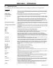
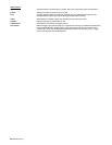
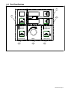
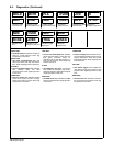
1
3
2
1 Process Set Up Push Button
2 Process Set Up LED
3 Program Selection LEDs
Process
Wire Type
Gas Type
Process Set Up
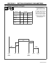
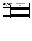
Table 6-1. Welding Wire And Gas Abbreviations*
Wire Description Wire Abbreviation Alloy Type Gas Type Gas Abbreviation
Steel STL E70, E100, E120 100% CO
2
,
90% Argon/10% CO
2
,
85% Argon/15% CO
2
,
75% Argon/25% CO
2
,
95% Argon/5% CO
2
,
95% Argon /5% O
2
,
98% Argon/2% O
2
CO2
C10
C15
C25
C5
OX5
OX2
Stainless Steel SS 308, 309, 312, 316 98% Argon, 2% O
2
(81Ar/18HE/1CO
2
Accu-pulse)
90HE/7-1/2Ar/2-1/2CO
2
MIG/RMD)
OX2
Tri Gas
Tri Gas
Cored Tubular Wire MCOR 71, 76, 86R, 409 90% Argon/10% CO
2
C10
98% Argon/2% O
2
OX2
Aluminum ALUM 4XXX, 5XXX 100% Argon ARGN
* Not all wire types may be available with your unit.