


OM-221 677 Page 8
SECTION 4 − INSTALLATION
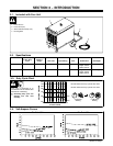
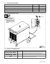
4-1. Selecting a Location
Position unit so air can circulate.
500 mm
500 mm
500 mm
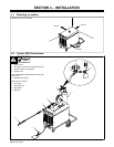
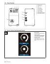
4-2. Typical MIG Connections
1 Power source
2 Work clamp (connect to receptacle as shown)
3 Cylinder (chain to running gear)
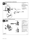
4 Cylinder valve
Open valve slightly so gas flow blows dirt from valve.
Close valve.
5 Regulator/Flow gauge
Install so face is vertical.
6 Flow adjust
7 Gas supply line
8 Wire feeder
9 MIG torch
1
4
5
6
3
7
8
2
9