


OM-221 677 Page 11
SECTION 5 − OPERATION
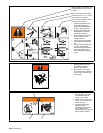
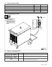
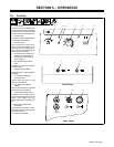
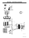
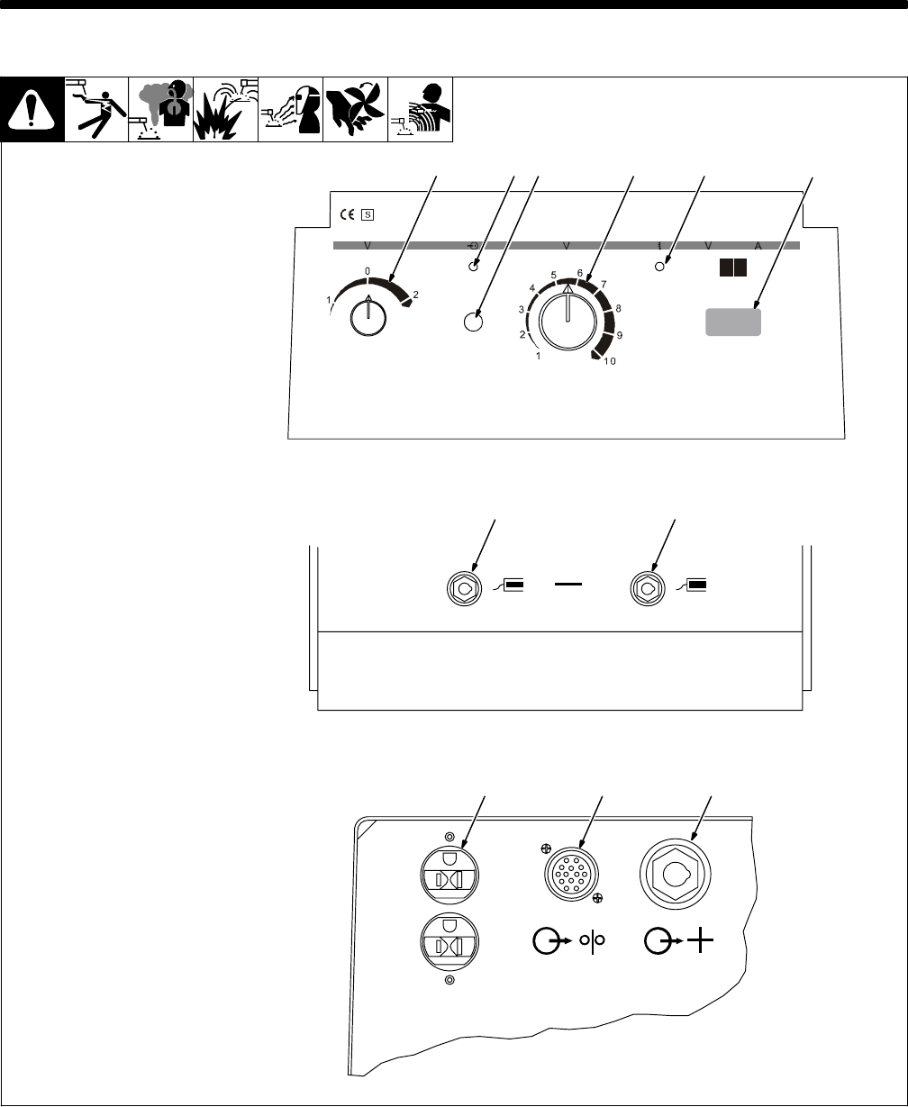
5-1. Controls
1 Power Switch
The power switch is a selector knob
which permits selection of operation
on either of the two available ranges
(I and II) and the center position is off.
2 Indicator Lamp
This lights up when the power switch
is placed in the ON position.
3 Protection Fuse
Fuse F protects the control circuit.
Should it become necesary to re-
place any fuse in the welding power
source, be sure to substitute with one
of the same size and rating.
4 Use this control to adjust weld
voltage 10 position switch. 20
weld setting, 10 high range (I),
10 low range (II).
5 High Temperature Shutdown
Light
This lights up when unit overheats
and shuts down.
6 Voltage/Amperage Meter.
Use toggle switch to select voltage or
amperage.
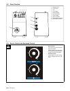
7 Low Inductance Negative
Output Terminal
Connect work lead here for most
“short-arc” applications.
8 High Inductance Negative
Terminal
Connect work lead here for stainless
steel and spray arc conditions.
9 115 AC Receptacle (optional)
Located on the rear panel is a recep-
tacle which provides power to the gas
heater, when welding with CO
2
shielding gas and for the cooling sys-
tem.
10 Wire Feeder Power Cable
Receptacle
Located on the rear panel is a recep-
tacle used to supply operating power
to the wire feed unit.
11 Positive Out Terminal
115 VAC
Front Panel
Back Panel
4
11109
7 8
6
51 32