


OM-1500-1 Page 15
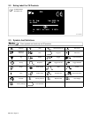
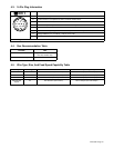
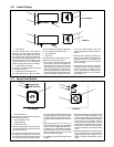
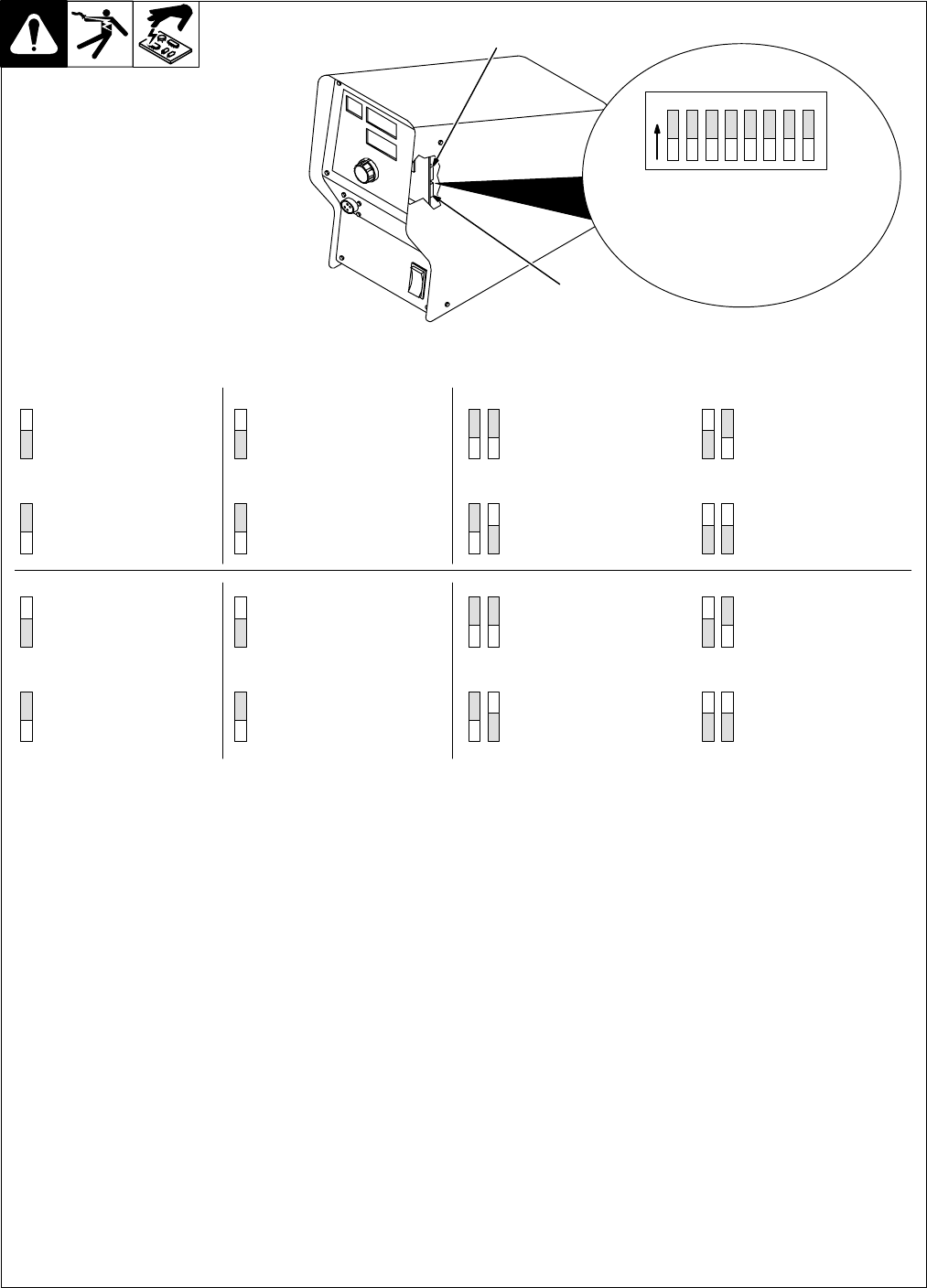
4-7. Setting Internal DIP Switches
1 DIP Switch S1
2 DIP Switch S4 (Not For Customer Use)
DIP switch S1 allows the user to make a num-
ber of choices affecting unit operation.
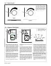
w Selecting Weld Amperage Or Wire Feed
Speed Display (S1-1)
If the front panel DIP is set in the display amps
position, the lower display (see Section 5-6)
shows amperage while the unit is welding at
an amperage value above 25 Amps and the
current detect override is in the Off position. If
the amperage display position is not used, the
lower display shows wire speed.
w Selecting Wire Feed Speed Value (S1-2)
The unit displays wire speed in units of inches
per minute (IPM) if the English/Metric wire
feed display DIP is in the English position. The
unit displays wire speed in meters per minute
(MPM) if the DIP is in the metric position.
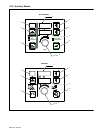
w Adjusting Range Limits (S1-3 & 4)
The lock feature provides a means of regulat-
ing unit settings, but still allows some level of
adjustment through the Adjust control. When
a lock position is used, the lock applies to all
programs. Two DIP switches are dedicated to
locking unit settings. Four possible combina-
tions of the two DIP switches provide the fol-
lowing settings: Locks Off, Locks On ±5%,
Locks On ±10%, and finally Locks On ±20%.
If the wire speed is at 300 IPM when the lock
DIP is activated, and the lock range is set at
±10%, the operator would have an adjustment
range from 270 to 330 IPM.
. To changing Lock %, proceed as follows:
Turn power Off
Place DIP switches S1-3&4 in the Off position
(see *3&4 above)
Turn power On and Off
Place switches 3&4 in desired new settings
Turn power On and Off.
Trigger Hold and Dual Schedule function nor-
mally when locks are enabled.
w Setting Display Hold Feature (S1-5)
If the display hold DIP is in the “Hold On” posi-
tion, the unit will hold the last weld information
for 5 seconds following weld termination. If
any front panel push button is pressed, or if the
Adjust control is activated, the display hold
feature is terminated.
w Setting Current Detect Override (S1-6)
Current detect override is used to disable run-
in when a welding power source is used that
doesn’t provide current feedback through the
14-pin receptacle.
w Defining Motor Speed (S1-7 & 8)
Switches 7 and 8 allow the user to define
whether the motor in use is normal speed
(50–780 inches per minute) or high speed
(90–1440 inches per minute).
802 808
1
2
12345678
O
N
1
2
34
5
678
2
1 34
5
6
78
34
34
7878
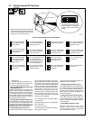
Position Settings And Results For DIP Switch S1
On = Front panel display
shows weld amperage
during welding.
Off = Front panel display
shows wire feed speed
during welding.
On = Front panel display
shows wire feed speed in
meters per minute.
Off = Front panel display
shows wire feed speed in
inches per minute.
3 On, 4 Off = Range limit
on voltage and wire feed
speed set at ±5%.
3 Off, 4 Off = Range limit-
ing disabled (locks Off).
3 On, 4 On = Range limit
on voltage and wire feed
speed set at ±20%.
3 Off, 4 On = Range limit
on voltage and wire feed
speed set at ±10%.
On = Front panel display
holds weld parameters
for 5 seconds following
trigger release.
Off = Front panel display
returns to preset upon trig-
ger release.
On = Current detect overri-
de. For welding power
sources that don’t provide
current feedback through
the 14-pin receptacle.
Off = Current must be de-
tected to go from run-in to
welding condition.
7 On, 8 Off = Reserved
for future use.
7 Off, 8 Off = Normal
speed motor (50–780
inches per minute)
7 On, 8 On = Reserved
for future use.
7 Off, 8 On = High speed
motor (90–1440 inches
per minute)
. In the DIP switch S1 illustrations,
the elevated slider on each switch
is show in white. For example, the
switches above are all in the Off
position.
. When DIP switch positions are changed, the
unit must be turned Off and then On again in
order for the new settings to be active. DIP
switches are only read on power up.
*