


OM-1500-1 Page 20
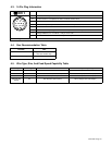
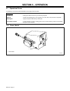
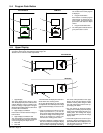
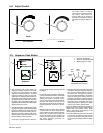
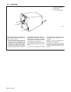
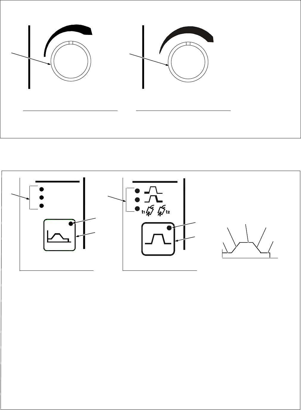
5-8. Adjust Control
Adjust
1
1 Adjust Control
The Adjust control is used to
change various sequence parame-
ters, and to select various se-
quences. Refer to the section for
the function in question for informa-
tion related to using the Adjust con-
trol.
1
Non-CE Models CE Models
Start
Crater
Pre/Postflow
Sequence
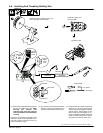
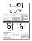
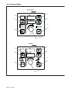
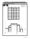
5-9. Sequence Push Button
• The Sequence push button allows the
selection of welding sequences. Five weld-
ing sequences are available. The default
sequence is the Weld sequence. The Weld
sequence is active on power up, and is indi-
cated when no welding sequence LEDs are
illuminated. Three welding sequence LEDs
are located above the Sequence push but-
ton: Start, Crater, and Preflow/Postflow. The
applicable LED illuminates to indicate which
welding sequence is active.
• The LED illuminates to indicate that a weld-
ing sequence display mode other than Weld
is activate. Welding sequences other than
Weld must be set prior to initiating the arc.
When the unit enters a welding state, all se-
quence display modes are terminated and
the weld display mode is activated.
If zero time is programmed for a timed se-
quence except for Weld, that sequence will
be skipped.
• In the weld sequence display mode the Se-
quence push button LED is Off , and all other
sequence LEDs are Off. When the Se-
quence push button is pressed, the Se-
quence push button and the Start LEDs illu-
minate. In this condition, the unit is in the
Start sequence display mode, and Start se-
quence parameters are shown in the dis-
plays.
• When the Sequence push button is pressed
a second time, the Start sequence LED
goes Off and the Crater sequence LED illu-
minates. The Sequence push button LED
remains illuminated. In this condition, the
unit is in the Crater sequence display mode,
and Crater sequence parameters are
shown in the displays.
• When the Sequence push button is pressed
a third time, the Crater sequence LED goes
Off and the Preflow/Postflow sequence
LED illuminates. The Sequence push but-
ton LED remains illuminated. In the Preflow
display mode the upper display shows the
preflow time and the lower display indicates
the abbreviation PRE, to inform the operator
that preflow time is displayed. If the upper
display push button is pressed, the Adjust
control can be used to adjust preflow.
If the lower display push button is pressed, the
Adjust control can be used to select between
preflow PRE and postflow POST. When
POST is selected, the upper display can be
used to specify postflow time.
• When the Sequence push button is pressed
a fourth time, all sequence LEDs and the
Sequence push button LED go off and the
unit returns to the welding sequence display
mode.
1
3
2
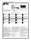
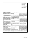
Welding Sequence Diagram
Preflow
Time
Start
Time
Weld
Time
Crater
Time
Postflow
Time
1 Sequence Push Button
2 Sequence Push Button LED
3 Welding Sequence LEDs
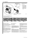
1
2
3
Non-CE Models CE Models