


OM-1500-1 Page 19
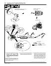
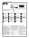
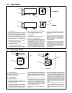
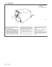
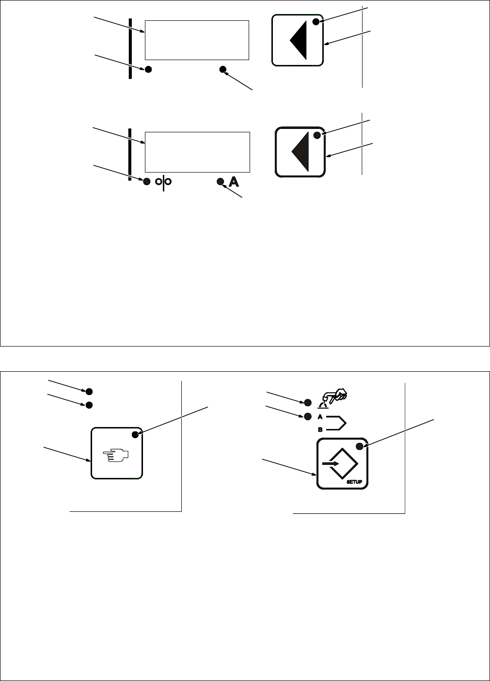
5-6. Lower Display
1 Lower Display
The lower display shows wire speed or
amperage. The unit displays and adjusts
only preset wire speed at idle. When the unit
is in a welding state, actual wire speed is dis-
played for the active welding sequence. If the
amps display DIP is set in the display amps
position (see Section 4-7), the lower display
shows amperage while the unit is welding.
2 Lower Display Push Button
Press button to choose between wire speed
or amperage functions.
3 Lower Display Push Button LED
The lower display push button LED illumi-
nates to indicate that information displayed
can be changed by the Adjust control.
4 Wire Speed LED
5 Amps LED
The LEDs below the display illuminate to in-
dicate which value is being shown.
• If the unit is in a welding state that does not
involve feeding wire, the unit displays the
weld sequence wire speed. At any time
during welding, the weld sequence wire
speed can be adjusted and overrides the
preset wire speed display. In other words,
if the Adjust control is activated while weld-
ing, the unit displays and permits adjust-
ment of the weld sequence wire feed
speed regardless of the active welding se-
quence.
• When the unit is displaying amperage, the
Amps LED illuminates. Amperage is only
displayed if the unit is in a welding state
and the amperage is above a minimum
value of 25 Amps.
• The display will read zero for amperage
readings below the amperage threshold,
prior to arc initiation. In addition, the am-
perage display feature is disabled if the
current detect override is in the On position
(see Section 4-7).
2
Wire Speed Amps
1
5
4
3
1
4
2
3
5
Non-CE Models
CE Models
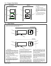
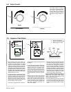
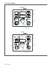
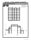
5-7. Setup Push Button
1 Setup Push Button
Press button to choose between trigger hold
or dual schedule functions.
2 Setup Push Button LED
3 Trigger Hold LED
4 Dual Schedule LED
• When the Setup button is pressed, the Set-
up push button LED illuminates and the Trig-
ger Hold LED flashes.
• The flashing LED indicates that the unit is in
the trigger hold display mode. In this mode
the upper display indicates HOLD and the
lower display indicates the trigger hold sta-
tus On/Off. Use the Adjust control to change
the trigger hold status or press the lower dis-
play push button. If trigger hold is turned On,
the trigger hold LED illuminates and stays
On.
• When trigger hold is On, the user must
press and hold the trigger for a predefined
amount of time (the trigger hold delay time–
see Section 5-10), then release it for the trig-
ger hold function to be active. To shut off the
weld when trigger hold is On, the user must
press and release the trigger.
• If a weld time is programmed, trigger hold is
disabled.
• When the Setup button is pressed a second
time, the dual schedule LED flashes. In this
mode the upper display indicates DUAL and
the lower display indicates dual schedule
status On/Off. Use the Adjust control to
change the dual schedule status if desired.
• Pressing the Setup button again exits the
Setup mode. The dual schedule LED stops
flashing to indicate the dual schedule status
is Off.
• While in the Setup mode, the active program
can be adjusted without deactivating the
trigger hold Setup mode operation. If the
trigger is activated, Setup mode(s) is termi-
nated.
Trigger Hold
Setup
Dual Schedule
1
2
3
4
Non-CE Models
2
1
3
4
CE Models