


OM-1580 Page 7
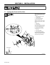
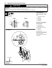
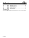
3-2. Outlet Cable, Weld Cable, And Gas Connections
Ref. ST-156 544
1 Outlet Cable Securing Knob
2 Outlet Cable Opening
3 Outlet Cable End
Loosen knob. Insert outlet cable
end into opening. Position as close
as possible to drive rolls without
touching. Tighten knob.
Connect 4-pin plug from outlet cable
to the 4-socket receptacle on the
motor mounting bracket.
4 Weld Cable Terminal
5 Weld Cable
Select and prepare weld cable ac-
cording to welding power source
Owner’s Manual.
6 Shielding Gas Fitting
7 Gas Hose
Gas fitting is located behind outlet
cable opening.
Connect gas hose from fitting on ro-
bot to shielding gas fitting on wire
drive assembly.
6
9/16 in
Tools Needed:
Connect To
Gas Fitting
7
Connect To Positive (+) Weld
Output Terminal On Welding
Power Source For Reverse
Polarity Weld Process Or
Connect To Negative (–) Weld
Output Terminal On Welding
Power Source For Straight
Polarity Weld Process.
4
5
1
2
3
On Robot
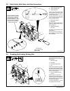
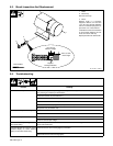
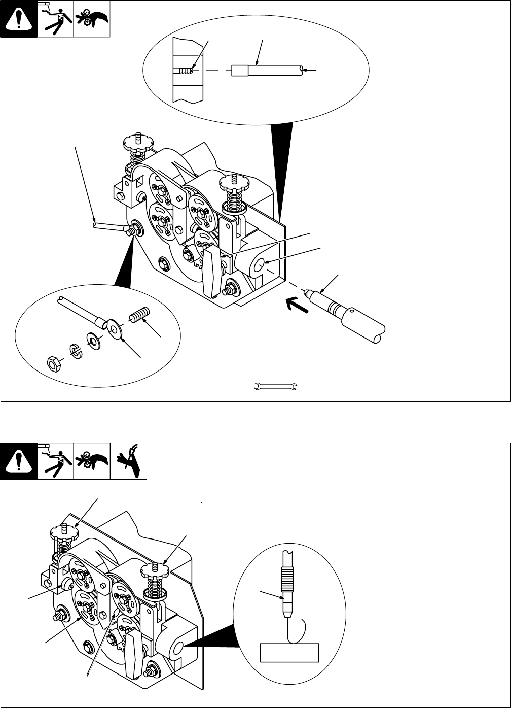
3-3. Threading And Feeding Welding Wire
ST-045 282-C / Ref. ST-156 798
Loosen wire from wire spool, cut off
bent wire, and pull 6 in (150 mm) of
wire off spool.
1 Wire Inlet Guide
2 Drive Roll
3 Intermediate Wire Guide
4 Gun
Thread wire through inlet guide,
along drive rolls, through intermedi-
ate guide and drive rolls, into outlet
cable, and out of the gun. Be sure
wire is in correct groove.
5 Pressure Adjustment Knob
And Arm
Close pressure roll assembly.
Check drive roll pressure by feed-
ing wire against a wood board or
concrete surface; wire should feed
steadily without slipping.
If pressure adjustment is neces-
sary, tighten pressure knobs.
1
WOOD
2
3
4
5
5