


OM-1580 Page 10
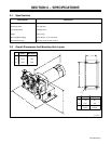
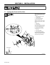
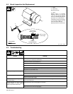
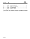
5-3. Brush Inspection And Replacement
1 Motor
2 Brush Cap
Remove brush cap.
3 Brush
Replace brush if it becomes
chipped or broken, or if less than
1/4 in. (6.4 mm) of brush material is
left. Do not include spring boss as
part of the 1/4 in. measurement.
Install brush so that curved surface
on end of brush matches curve of
motor, and secure with cap.
Repeat procedure for other brush.
ST-137 390-C / S-0816
1
2
3
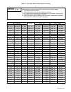
Tools Needed:
1/4 in (6 mm)
Minimum Length
5/8 in (16 mm)
New Length
Replace
Damaged Brushes
5-4. Troubleshooting
Trouble Remedy
Wire feeds erratically. Adjust drive roll pressure by turning pressure adjustment knob(s) 1/4 turn clockwise until wire stops slip-
ping. Check gun contact tip for obstructions.
Check size of drive roll (see Section 3-1).
Replace drive roll if worn (see Section 3-1).
Clean drive roll, and check wire spool hub tension.
Check and secure motor plug connection (see Section 3-2).
Align drive rolls (see Section 5-2).
Wire stops feeding while welding. Align drive rolls (see Section 5-2).
Replace motor.
Motor runs slowly. Reduce load.
Check for correct input voltage.
Motor runs at full speed regardless of
wire speed setting.
Have Factory Authorized Service Station/Service Distributor check digital wire drive motor Tachometer
board and encoder disc.
Operation Module servo light on, Teach
Pendant display on, servo warning
light(s) off (A1D-4RV model only).
Check and secure servo warning light(s) connection.
Replace burned out servo warning light(s).