


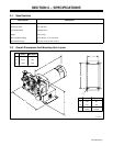


OM-1580 Page 9
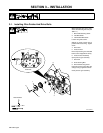
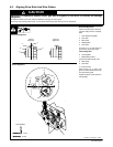
5-2. Aligning Drive Rolls And Wire Guides
CAUTION
IMPROPER CLEARANCE between motor gear and drive gears on four-drive roll models can damage
equipment.
• Maintain 0.003 in (0.076 mm) clearance between motor gear and drive gears.
Gears may wear severely, bind, break, or cause erratic wire feed if proper clearance is not maintained.
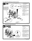
Correct Incorrect
AlignmentAlignment
S-0629-A / ST-045 282-C / S-0087
Horizontal Alignment
View is from top of drive rolls look-
ing down with pressure assembly
open.
1 Drive Roll Securing Bolt
2 Drive Roll
3 Wire Guide
4 Welding Wire
5 Drive Gear
Turn bolt in or out until drive roll
groove lines up with wire guide.
Vertical Alignment
6 Housing Bolts
7 Weld Cable Terminal
Loosen bolts and terminal nut(s).
8 Wire Guide
9 Drive Roll
10 Pressure Roll
Slide housing up or down until
groove in drive roll and pressure roll
line up with wire guide.
Tighten hardware. Close pressure
roll assembly.
1
9/16 in
7/16 in
Tools Needed:
Horizontal Alignment
Vertical Alignment
2
3
4
5
7
6
7
8
10
8
9